
Ever flipped through a mast catalogue and wondered what all those profile numbers and spec tables actually mean? You're not alone. Understanding aluminum sailboat mast extrusion starts with grasping what the term describes: both a manufacturing process and the product it creates.
At its core, an aluminum mast extrusion is a continuous metal profile produced by forcing a heated aluminum billet through a precisely shaped die. The extrusion process works much like squeezing toothpaste from a tube, except the opening is engineered to create a specific cross-sectional shape. What emerges is an elongated piece with the same profile as the die opening, maintaining a uniform cross-section along its entire length. This consistency is exactly what makes extruded profiles ideal for sailboat masts and booms.
This article breaks down the engineering behind these profiles so you can confidently interpret spec sheets, understand alloy choices, evaluate profile geometry, and recognize what matters for corrosion protection. Whether you're replacing rigging on your mast boat or specifying components for a refit, the concepts ahead will give you the foundation to make informed decisions.
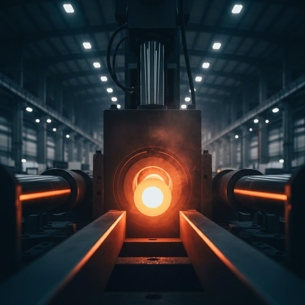
An aluminum mast extrusion is specifically an aluminum profile produced via hot extrusion, designed to serve as a sailboat mast or boom section. The billet is heated to approximately 800-925°F before being pushed through the die under immense hydraulic pressure. Temperature control is critical here because it determines the final characteristics of the metal, including hardness and surface finish.
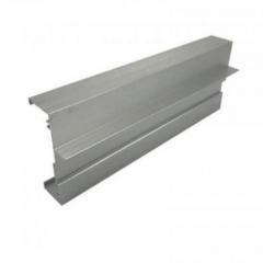
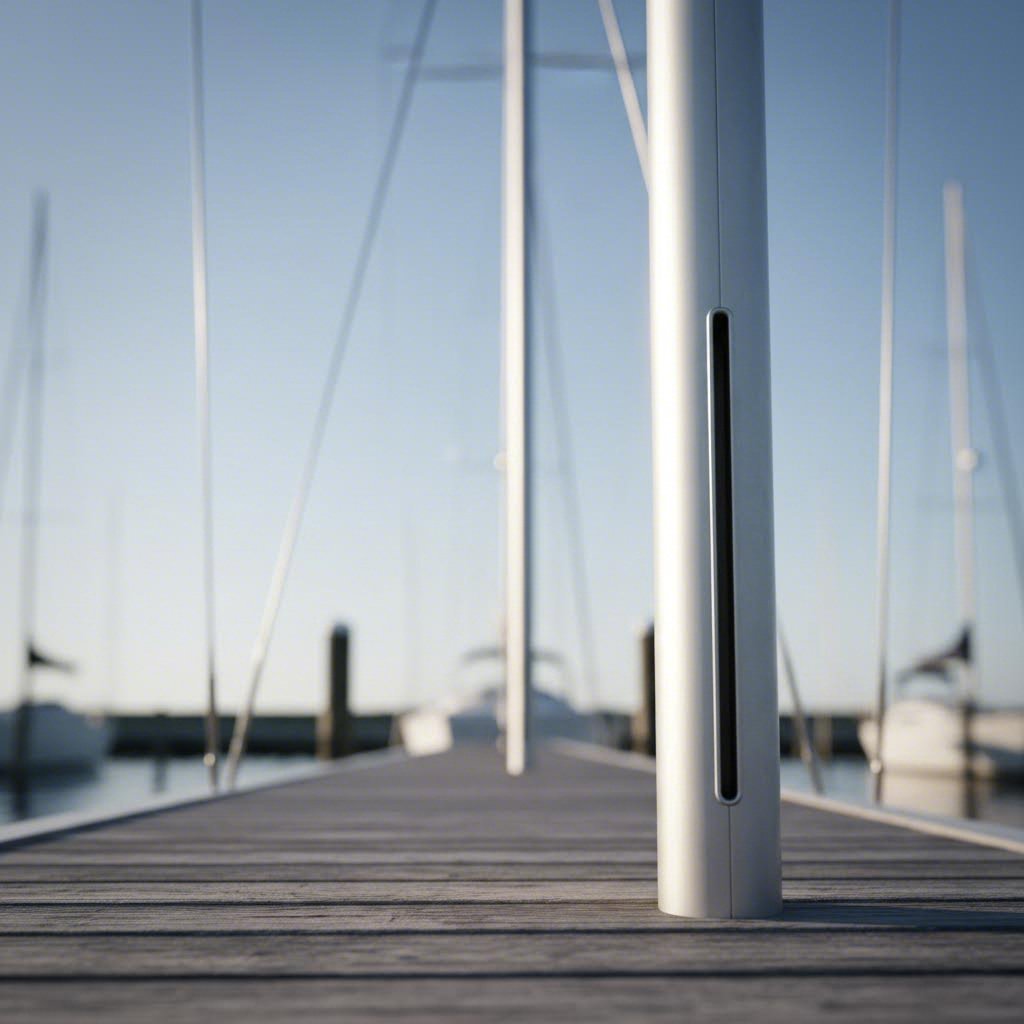
The result is a profile that can incorporate complex features directly into its shape: integrated sail track slots, internal cable channels, and precisely calculated wall thicknesses. All of this comes from a single pass through the die, which is why extrusion delivers such remarkable consistency from one meter to the next.
When you look at sailboat masts across marinas worldwide, aluminum dominates for good reason. Wood, the traditional choice, demands intensive maintenance and lacks the strength-to-weight consistency modern rigs require. Carbon fiber offers superior stiffness and weight savings, but at a price point that puts it out of reach for most production boats. Carbon masts also require specialized repair techniques that aren't available at every boatyard.
Aluminum sits in the practical middle ground. It delivers adequate strength, reasonable weight, good corrosion resistance in marine environments, and a cost structure that works for production sailboats. Repairs are straightforward with standard welding techniques, and replacement sections are readily available.
Aluminum extrusion technology made offshore sailing accessible to everyday sailors by delivering consistent, affordable mast sections that perform reliably season after season.
The extrusion process itself contributes to this accessibility. Once a die is created, producing additional profiles becomes economical at scale. This manufacturing efficiency translates directly into lower costs for boat builders and sailors alike, which is why aluminum remains the default material for production sailboat masts.
So how does a solid cylinder of aluminum become the precisely shaped mast for boat applications you see at the chandlery? The manufacturing sequence involves several carefully controlled stages, each affecting the final profile's mechanical properties and dimensional accuracy. Understanding this process helps you appreciate why marine aluminum extrusions command the quality standards they do.
The journey from raw material to finished mast section follows a specific sequence. Each stage builds on the previous one, and skipping or rushing any step compromises the final product. Here's how aluminum boat extrusions come to life:
The entire sequence typically produces profiles 8-24 feet long, which are then cut and processed to match specific mast requirements for booms and extrusions used in sailing applications.
Imagine the die as more than just a hole in a steel plate. It's actually a precision-engineered tool that encodes the entire structural and functional geometry of your finished mast section. Every feature you see in a completed profile originates in the die design.
The die determines wall thickness distribution across the profile. Mast sections often feature variable wall thicknesses, with thicker material where stress concentrations occur and thinner walls where weight savings matter most. Die designers must account for how aluminum flows differently through areas of varying thickness. Thin-walled sections and sharp edges require careful attention because metal flows faster through wider openings and slower through restricted areas.
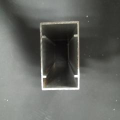
Internal voids present another design challenge. Hollow mast profiles require split dies or porthole dies that create internal chambers while maintaining structural integrity. The extrusion ratio, which measures the difficulty of achieving a particular shape, typically falls between 10 and 150 for practical applications. Solid profiles work well around a ratio of 30, while hollow profiles like mast sections often target ratios around 45.
External features like integrated sail track slots emerge directly from the die geometry. Rather than machining these features afterward, the extrusion process creates them in a single pass. This integration reduces manufacturing steps and ensures consistent dimensions along the entire profile length.
Press tonnage matters here too. Larger, more complex profiles with intricate internal geometries demand higher-tonnage presses to force the aluminum through the die at consistent speeds. The relationship is straightforward: as profile complexity increases, so does the required press capacity. This is why specialized marine aluminum extrusions often come from facilities with substantial press capabilities.
Die designers also manipulate metal flow speed using sizing belts of varying lengths. Areas with thinner walls or greater distance from the press center receive shorter sizing zones to accelerate flow, while thicker sections get longer zones to slow the metal down. The goal is uniform exit velocity across the entire profile cross-section, which prevents warping and dimensional inconsistencies.
With the manufacturing process clear, the next logical question becomes: which aluminum alloy should that billet be made from in the first place?
Not all aluminum is created equal. When you're specifying a mast for sailboat applications, the alloy designation on that spec sheet tells you more about performance potential than almost any other number. Three grades dominate the conversation: 6061-T6, 6063-T5, and 7075. Each brings a distinct combination of strength, workability, and corrosion behavior to the table.
Think of alloy selection as a decision tree rather than a single answer. Your choice depends on what matters most for your specific application: maximum strength, ease of fabrication, surface finish quality, or long-term durability in saltwater environments. Understanding what each alloy offers helps you navigate that decision with confidence.
These three alloys represent different points on the performance spectrum. The table below breaks down their key characteristics so you can compare them side by side:
| Property | 6061-T6 | 6063-T5 | 7075-T6 |
|---|---|---|---|
| Ultimate Tensile Strength | 45,000 psi (310 MPa) | 28,000 psi (193 MPa) | 83,000 psi (572 MPa) |
| Yield Strength | 40,000 psi (276 MPa) | 23,000 psi (159 MPa) | 73,000 psi (503 MPa) |
| Corrosion Resistance | Good | Excellent | Poor |
| Weldability | Excellent | Excellent | Poor |
| Extrudability | Good | Excellent | Moderate |
| Typical Mast Application | Production sailboat masts, structural components | Lower-load applications, architectural profiles, booms | Rarely used for masts; aerospace and high-stress applications |
You'll notice 6061-T6 sits in the middle ground across most categories. It's not the strongest, not the most corrosion-resistant, and not the easiest to extrude. But it delivers a balanced combination that works exceptionally well for marine structural applications.
The strength figures tell an interesting story. 7075-T6 offers nearly twice the tensile strength of 6061-T6, which sounds appealing until you consider the tradeoffs. That extra strength comes at the cost of corrosion resistance and weldability, both critical factors for a mast that will spend years in a saltwater environment and may need fitting repairs along the way.
Walk through any marina and the masts you see overhead are almost certainly 6061-T6. This alloy earned its dominant position through a combination of properties that align perfectly with what sailboat masts actually need.
Strength comes first. With an ultimate tensile strength of at least 42,000 psi and yield strength of at least 35,000 psi, 6061-T6 handles the dynamic loads that rigging imposes on a mast section. Forestay tension, backstay loads, and the compression forces from a fully loaded rig all fall within this alloy's comfortable working range for properly sized sections.
Weldability matters more than many sailors realize. Mast fittings, spreader brackets, and tangs often require welding during manufacture or repair. 6061-T6 welds readily using conventional TIG and MIG techniques, and the heat-affected zone retains reasonable strength after proper post-weld treatment. This fabrication flexibility keeps manufacturing costs down and makes field repairs practical.
Corrosion resistance in marine environments is adequate with proper surface treatment. While not as naturally resistant as 6063, anodized 6061-T6 performs well in saltwater service when maintained appropriately. The alloy's silicon and magnesium composition creates a stable oxide layer that responds well to anodizing processes.
Extrudability rounds out the picture. 6061 flows through dies cleanly enough to produce the complex hollow profiles that modern mast sections require. Integrated sail tracks, internal halyards channels, and variable wall thicknesses all emerge from the extrusion process without excessive die wear or surface defects.
You might encounter 6063-T5 in certain mast components, particularly booms, spinnaker poles, and lower-load applications. This alloy excels where surface finish and extrudability matter more than raw strength.
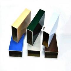
6063 is the preferred material for custom aluminum extrusions when visual appeal takes priority. Its smoother surface finish after extrusion makes it ideal for architectural applications and visible components where aesthetics count. The alloy also flows more easily through complex die geometries, enabling intricate profile shapes at lower production costs.
However, the strength numbers tell you why 6063 rarely appears in primary mast sections. At roughly 60% of 6061's tensile strength, it simply cannot handle the same loads in equivalent cross-sections. For a boom that sees lower stress levels than the mast itself, 6063 may work fine. For the mast carrying your entire rig load, 6061-T6 remains the safer choice.
On paper, 7075 looks tempting. Nearly double the strength of 6061 means you could theoretically use lighter sections for the same load capacity. Aerospace engineers love this alloy for aircraft structures where every gram matters. So why don't mast manufacturers use it?
Corrosion resistance is the first problem. 7075's high zinc and copper content makes it significantly more vulnerable to corrosion than 6000-series alloys, particularly stress corrosion cracking in marine environments. A mast lives in one of the harshest corrosion environments imaginable: constant salt spray, standing water in the step, and dissimilar metal contacts at every fitting. 7075 would require aggressive protective treatments and vigilant maintenance to survive.
Weldability presents the second obstacle. 7075 is considered one of the more challenging aluminum alloys to weld due to its high zinc content, which contributes to hot cracking susceptibility. The heat-affected zone loses significant strength, and achieving reliable welds requires specialized techniques that most boatyards cannot perform. When a spreader bracket needs repair or a fitting requires modification, 7075 creates problems that 6061 simply doesn't.
Cost adds a final consideration. 7075 typically commands a 30-50% premium over 6061, and the machining challenges increase production costs further. For the marginal weight savings possible in a mast application, the economics rarely justify the material choice.
The alloy decision ultimately comes down to matching material properties to application requirements. For production sailboat masts, 6061-T6 delivers the right balance. Understanding why helps you evaluate spec sheets with confidence and recognize when alternative alloys might serve specific purposes in your rig.
With alloy selection clarified, the next consideration is how that material gets shaped into the specific cross-sectional geometry that determines your mast's structural behavior.
When you slice through a mast and look at the cross-section, you're seeing the result of careful engineering decisions. That shape isn't arbitrary. It determines how your mast bends under load, how much drag it creates, and how well it integrates with your sail. Understanding these profile geometries helps you make sense of why different yacht mast parts look the way they do.
The extrusion process creates profiles with a uniform cross-section along their entire length. This is both a strength and a constraint. Engineers can't taper the section or vary its shape from bottom to top the way they might with a custom-built carbon spar. Instead, they optimize the cross-sectional geometry itself, choosing shapes that deliver the right stiffness characteristics for specific rig types and sailing applications.
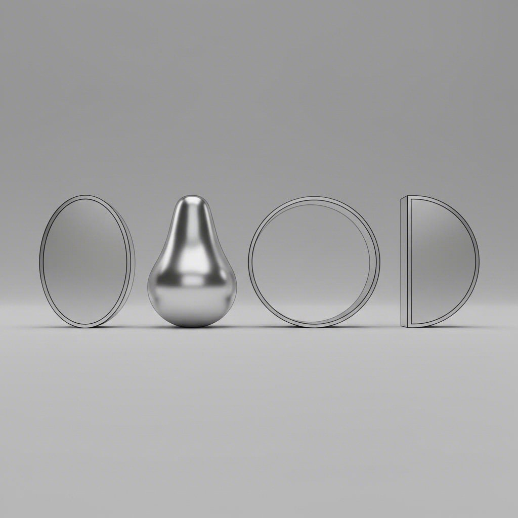
Imagine looking down at an oval mast section. The longer axis runs fore-and-aft, while the shorter axis runs athwartships (side to side). This shape creates an intentional imbalance in bending resistance. The mast becomes stiffer in the fore-aft direction and more flexible athwartships.
Why would you want that? Fractional rigs provide the answer. On a fractional rig, the forestay attaches partway up the mast rather than at the masthead. This concentrates significant fore-aft loads at the hounds, where the stays attach. An oval section's higher fore-aft stiffness handles these loads efficiently. Meanwhile, the relative flexibility athwartships allows the mast to bend sideways in a controlled manner, which helps depower the sail in gusts.
The radius of gyration explains this behavior mathematically. For an elliptical section, the radius of gyration value lies on an elliptical line, being greater along the longer axis but closer to the center where the section is narrower. Load the mast vertically, and it bends more easily in the direction with less section width.
Pear-shaped profiles take the oval concept further. The trailing edge tapers to a narrower point, creating an aluminium aerofoil extrusion that reduces aerodynamic drag. This shape integrates cleanly with the mainsail luff, allowing smoother airflow over the critical lee side of the sail. Racing boats and performance cruisers often specify pear-shaped sections for this reason.
The aerodynamic benefit matters more than you might expect. A round mast creates turbulent flow that disrupts the sail's leading edge. A pear-shaped profile acts more like a wing's leading edge, guiding air smoothly onto the sail surface. The result is better lift and less drag, particularly when sailing close-hauled.
Round sections take a fundamentally different approach. Instead of optimizing for a specific load direction, they offer equal stiffness in all directions. The radius of gyration sits at the same distance from center regardless of which way you measure.
This uniformity makes round profiles predictable and forgiving. They bend the same amount whether the load comes from forestay tension, shroud loads, or a combination of both. For smaller dinghies and cruising boats where simplicity matters more than aerodynamic refinement, round aluminum masts deliver reliable performance without complexity.
As one experienced sailor noted in a discussion about mast sections, round shapes are employed because you want the center of gyration to be equal around the perimeter of the column. A tear-drop section would have higher resistance to bending fore and aft compared to side to side, which creates unpredictable behavior when side loads and fore-aft loads combine.
Round sections also work well for free-standing masts on cat-rigged boats. Without stays to control bend direction, the mast needs to respond consistently regardless of wind angle. A round profile delivers that consistency.
D-section profiles serve a different purpose entirely. These flat-backed shapes appear primarily on booms, spinnaker poles, and other yacht mast parts where one flat face aids fitting attachment. The flat surface provides a stable mounting plane for hardware, while the curved portion maintains structural efficiency. You won't typically see D-sections used for primary masts, but they're common throughout the rest of the rig.
Here's the engineering reality: extrusion produces a uniform cross-section along the full profile length. You can't vary the shape from mast step to masthead the way a custom builder might. This constraint shapes how engineers approach mast design.
Rather than varying the section, designers optimize wall thickness distribution within the chosen profile geometry. Thicker walls in high-stress areas provide strength where needed, while thinner walls elsewhere save weight. The die encodes all of this into a single, consistent shape.
Profile geometry choices also compensate for the uniform-section limitation. A fractional rig mast might use an oval section with specific fore-aft to athwartships ratios calculated to handle the expected load distribution. The geometry does the work that section variation would do in a custom spar.
Spreaders and diamonds further divide the mast into shorter effective lengths, reducing the slenderness ratio and increasing buckling resistance. This allows engineers to use lighter sections than would otherwise be possible with a uniform profile.
Choosing the right profile geometry depends on your rig type, boat class, and sailing priorities. Here's how the main profile families map to typical applications:
The parts of a mast work together as a system. Profile geometry interacts with wall thickness, alloy choice, and rig configuration to determine overall performance. A Dwyer aluminum mast or similar production section represents a carefully calculated balance of these factors for its intended application.
Understanding profile geometry gives you the foundation to interpret what you see in mast catalogues. But those catalogues also contain engineering parameters that describe exactly how a given section will behave under load.
Ever opened a mast catalogue and felt like you needed an engineering degree to make sense of it? You're looking at rows of numbers labeled Ix, Iy, section modulus, and EI, but what do they actually tell you about how that mast will perform on your boat? These parameters aren't just abstract figures. They describe exactly how a mast section resists bending, how much it weighs, and whether it's appropriate for your rig type.
Understanding a mast extrusion spec sheet transforms you from a passive buyer into someone who can evaluate whether a particular section actually suits your application. The numbers encode real-world behavior, and once you know how to read them, you'll spot the differences between sections that look similar but perform very differently under load.
These four parameters appear on virtually every mast extrusion spec sheet. Each describes a different aspect of how the section behaves when forces act on it. Let's break them down one at a time.
The section modulus is a cross-sectional geometric property that determines how well a structural element resists bending. In practical terms, it tells you the stress that develops at the mast's outer surface when a bending load is applied. A higher section modulus means lower stress for the same load, which translates to a stronger mast that's less likely to yield or fail.
The calculation is straightforward: section modulus equals the moment of inertia divided by the distance from the neutral axis to the outermost fiber of the section. For mast applications, you'll see separate values for each axis because the section isn't symmetrical in both directions.
Mast moment of inertia measures how the material in a cross-section is distributed relative to a bending axis. Think of it as a measure of the section's resistance to bending. Material located farther from the center contributes more to the moment of inertia than material near the center. This is why hollow profiles work so well for masts. They place material at the outer edges where it does the most good, rather than wasting weight in the middle.
You'll encounter two moment of inertia values on any mast extrusion spec sheet:
The axis naming can feel counterintuitive at first. Just remember: the subscript tells you which axis you're rotating around, not which direction the mast bends. A high Iy value means the mast resists fore-aft bending well, which matters for handling forestay and backstay loads.
EI represents bending stiffness, the product of the material's elastic modulus (E) and the moment of inertia (I). While moment of inertia describes the geometry alone, EI incorporates the material properties too. For aluminum masts, E is essentially constant across common alloys, so EI differences between sections come primarily from geometry differences. A higher EI means a stiffer mast that deflects less under the same load.
| Parameter | Definition | Units | What Higher Values Mean |
|---|---|---|---|
| Ix (Moment of Inertia, fore-aft axis) | Resistance to athwartships bending based on material distribution | cm4 or mm4 | Greater resistance to side-to-side bending; stiffer athwartships |
| Iy (Moment of Inertia, athwartships axis) | Resistance to fore-aft bending based on material distribution | cm4 or mm4 | Greater resistance to fore-aft bending; handles forestay loads better |
| Section Modulus (Wx or Wy) | Moment of inertia divided by distance to outermost fiber | cm3 or mm3 | Lower surface stress under bending; higher load capacity before yield |
| EI (Bending Stiffness) | Elastic modulus multiplied by moment of inertia | N·m2 or kN·m2 | Less deflection under load; stiffer overall mast behavior |
When comparing marine aluminium extrusions, pay attention to the ratio between Ix and Iy. An oval section designed for a fractional rig will show a higher Iy relative to Ix, reflecting its optimization for fore-aft loads. A round section shows nearly equal values in both directions.
Beyond the structural parameters, two practical specifications deserve close attention: wall thickness and weight per meter. These numbers connect directly to real-world performance in ways that matter every time you sail.
Wall thickness affects both strength and weight simultaneously. Thicker walls increase the moment of inertia and section modulus, making the mast stronger and stiffer. But that extra material adds weight, and weight aloft has consequences. Every kilogram at the masthead reduces your boat's righting moment and increases pitching inertia. The mast swings through a longer arc when the boat pitches, making motion more pronounced and recovery slower.
The Selden catalogue presents mast sections with weight figures in kg/m, allowing direct comparison between profiles. A small difference in wall thickness compounds over the full mast height. Imagine two sections differing by 0.3 kg/m on a 15-meter mast. That's 4.5 kg of additional weight aloft, enough to noticeably affect how the boat feels in a seaway.
Mast manufacturers balance these tradeoffs carefully. They specify wall thickness distributions that provide adequate strength at critical stress points while minimizing weight elsewhere. The die geometry encodes these decisions, creating sections with variable wall thickness optimized for the expected load patterns.
Fractional rigs and masthead rigs impose fundamentally different load distributions, which translates directly to different Iy requirements when specifying a section. A fractional rig concentrates fore-aft loads at the hounds, where the forestay attaches partway up the mast. This creates high local bending moments that demand a section with substantial Iy. The mast below the hounds sees compression primarily, while the section above experiences both compression and significant bending.
Masthead rigs distribute loads more evenly along the mast length. The forestay attaches at the top, so fore-aft bending moments are lower at any given point. This allows masthead rig masts to use sections with lower Iy values relative to their overall size, or to achieve the same safety margins with lighter sections.
When you're evaluating a mast extrusion spec sheet, consider your rig type first. A section that works beautifully on a masthead cruiser may be underspecified for a fractional racing boat of similar displacement. The Iy value tells you whether the section can handle the fore-aft loads your rig configuration imposes.
Understanding these specifications puts you in a position to have informed conversations with riggers and suppliers. You can evaluate whether a proposed section actually matches your boat's requirements, rather than simply accepting whatever gets recommended. That knowledge becomes particularly valuable when you're sourcing replacement sections or specifying components for a refit.
Of course, even the best-specified mast section needs protection from the marine environment. The next consideration is how aluminum behaves in saltwater and what you can do to maximize its service life.
Here's something that surprises many sailors: aluminum is actually among the most corrosion-prone metals in the galvanic series. That sounds alarming given how many masts are made from it. But the reality is more nuanced. Aluminum survives beautifully in marine environments when you understand its corrosion behavior and take straightforward precautions. Ignore those precautions, and aluminum mast corrosion can compromise your rig faster than you'd expect.
Three distinct corrosion mechanisms threaten aluminum mast extrusions in saltwater service. Each works differently, and each requires a different prevention strategy. Understanding all three helps you protect your investment and catch problems before they become expensive.
The first mechanism is general oxidation. When exposed to air, aluminum almost instantly develops a tough, transparent oxide layer that acts as a natural corrosion inhibitor. This passive film is self-healing. Scratch it, and a new layer forms within moments. Even underwater, provided the water contains dissolved oxygen and moves freely, this protective coating maintains itself. General oxidation is largely self-limiting for this reason, which explains why raw aluminum performs so well on workboat hulls and commercial vessels.
The second mechanism is galvanic corrosion, which occurs whenever aluminum contacts a dissimilar metal in the presence of an electrolyte. Saltwater is an excellent electrolyte, but even freshwater, humidity, spray, or rain will facilitate the reaction. This is where aluminum's position on the galvanic series becomes critical.
The third mechanism is crevice corrosion, sometimes called poultice corrosion. This happens when stagnant water becomes trapped against aluminum in an oxygen-starved environment. Without oxygen, the protective oxide layer cannot form or repair itself. The aluminum becomes active and corrodes, producing aluminum hydroxide, a white powdery byproduct that resembles freezer-burned ice cream.
Imagine your mast as a battery terminal. In the galvanic series, virtually all other metals except zinc and magnesium are nobler than aluminum. This means aluminum corrodes preferentially whenever it contacts another metal while both are exposed to moisture. The further apart the two metals sit on the galvanic series, the faster the aluminum deteriorates.
Stainless steel fittings present a moderate risk. While stainless will cause aluminum to corrode at contact points, the rate isn't especially fast. The two metals are considered moderately compatible, which is why stainless hardware appears throughout aluminum rigs. However, the combination still requires attention.
Bronze and copper alloys are far more dangerous. These metals sit much further from aluminum on the galvanic series and are considered entirely incompatible. A bronze fitting mounted directly to an aluminum mast creates an aggressive galvanic cell that will pit the aluminum aggressively. Brass hardware poses the same risk.
Carbon fiber deserves special mention. Many sailors don't realize that carbon fiber is highly noble relative to aluminum, making it a significant galvanic corrosion sailboat mast risk. Carbon spreaders, carbon boom vangs, or carbon components in direct contact with an aluminum mast can accelerate corrosion at the interface. This combination requires careful isolation.
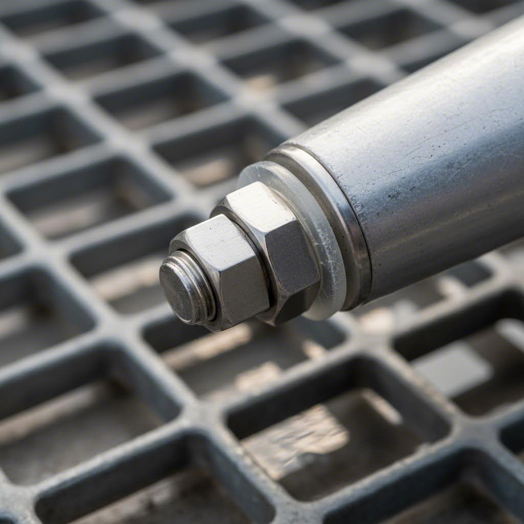
Practical mitigation involves breaking the electrical connection between dissimilar metals. Use isolation tape between fitting bases and the mast surface. Install plastic or nylon washers under fastener heads and between hardware and aluminum. Apply dielectric grease to threads and contact surfaces to exclude moisture and prevent the electrolyte from completing the galvanic cell. These simple measures dramatically extend the life of your fittings and the mast section beneath them.
An anodized aluminum mast has undergone an electrochemical process that thickens the natural oxide layer far beyond what forms naturally. Standard anodizing for marine applications typically produces a coating of 25-50 micrometers. Type III hard anodizing in this thickness range provides a good balance between wear resistance and the ability to withstand mechanical stresses without cracking.
Anodizing differs fundamentally from paint or powder coating. Paint sits on top of the aluminum surface and can chip, peel, or blister when breached. Once water gets under paint, poultice corrosion begins at the breach and spreads outward, lifting more paint as it progresses. Anodizing, by contrast, is integral to the aluminum itself. It cannot peel because it is the surface, not a coating on top of it.
This distinction matters for marine aluminum corrosion protection because hardware installations inevitably damage any surface treatment. Fasteners, spreader brackets, and tangs all create potential entry points for moisture. With paint, these breaches propagate. With anodizing, damage remains localized. You can touch up small scratches in an anodized surface with appropriate sealants, whereas painted aluminum often requires stripping and recoating entire sections once corrosion begins.
Annual rig inspections should focus on the areas most vulnerable to corrosion. Here's what to look for:
When you find minor surface corrosion, clean the area thoroughly, remove loose oxide, and seal with a marine-grade sealant or touch-up anodizing product. Deeper pitting or structural compromise requires professional evaluation. A rigger can assess whether the section retains adequate strength or needs replacement.
The key to long mast life is vigilance. Catch corrosion early, address it promptly, and maintain proper isolation at all dissimilar metal contacts. An aluminum mast treated this way will deliver decades of reliable service.
With corrosion behavior understood, the final step is matching all of these factors, alloy, geometry, specifications, and protection, to your specific boat and rig type.
You've absorbed the engineering fundamentals. Now comes the practical question: how do you actually select the right mast section for your specific boat? Whether you're a sailor replacing a damaged spar, a rigger specifying components for a customer, or an OEM buyer sourcing profiles for production boats, the decision framework follows the same logic. Match the section specifications to your vessel category and rig type, then decide whether standard catalogue profiles meet your needs or whether a custom extrusion makes sense.
Think of this as a sailboat mast sizing guide built around real-world categories rather than abstract engineering parameters. The spec sheet numbers you learned to read in the previous section now become selection criteria. Displacement, rig configuration, and intended use all factor into the equation.
The fundamental distinction starts with how your rig distributes loads. A fractional rig has the forestay attached lower on the mast, typically at 7/8 or 3/4 of the mast height. This concentrates significant fore-aft loads at the hounds. The mast section below the hounds experiences primarily compression, while the section above handles both compression and substantial bending moments. This load concentration demands higher Iy values to resist fore-aft deflection.
Masthead rigs work differently. With the forestay attached at the very top, loads distribute more evenly along the mast length. Fore-aft bending moments at any given point are lower than on a comparable fractional rig. This allows masthead configurations to use sections with relatively lower Iy values, or to achieve equivalent safety margins with lighter profiles.
Boat displacement adds another layer to the decision. Heavier boats generate higher rig loads simply because the sails must produce more force to move the hull. A 2,000 kg dinghy and a 15,000 kg offshore cruiser might both use fractional rigs, but the section specifications differ dramatically.
The table below maps rig type and displacement range to recommended profile characteristics. Use it as a starting point for conversations with riggers and suppliers:
| Boat Category | Typical Displacement | Rig Type | Profile Characteristics | Recommended Alloy |
|---|---|---|---|---|
| Dinghy / Small Daysailer | Under 500 kg | Fractional or unstayed | Round or oval section; lighter wall thickness; lower Iy requirements | 6061-T6 or 6063-T5 |
| Sportboat / One-Design Racer | 500 - 2,000 kg | Fractional (7/8 or 3/4) | Oval or pear-shaped; moderate wall thickness; higher Iy for fractional rig mast specification | 6061-T6 |
| Cruiser-Racer | 2,000 - 8,000 kg | Fractional or masthead | Oval section; medium-heavy wall; balanced Ix/Iy ratio for versatility | 6061-T6 |
| Offshore Cruiser | 8,000 - 20,000 kg | Masthead (typically) | Robust oval or round section; heavier wall thickness; emphasis on durability over weight savings | 6061-T6 |
| Performance Offshore / Superyacht | Over 20,000 kg | Varies | Custom profiles common; high section modulus; often OEM aluminum mast profiles | 6061-T6 (or carbon fiber) |
Notice how 6061-T6 dominates across categories. The alloy's combination of strength, weldability, and corrosion resistance makes it the default choice regardless of boat size. Only in the lightest applications, where loads are minimal and surface finish matters, does 6063-T5 become a reasonable alternative.
One-design classes add a specific constraint: class rules often mandate particular mast sections to ensure fair competition. If you're racing a J/22, Etchells, or similar one-design boat, the class association specifies exactly which profile you must use. Check your class rules before ordering anything.
Standard catalogue sections cover the vast majority of applications. Major mast manufacturers maintain inventories of proven profiles sized for common boat categories. These sections benefit from years of refinement, predictable availability, and competitive pricing. For most sailors and riggers, selecting from existing catalogue options is the practical path.
Custom aluminum mast extrusion becomes relevant in specific circumstances. OEM builders producing boats in volume may find that a purpose-designed profile optimizes performance or reduces assembly costs. Class-rule-specific requirements sometimes demand profiles that don't exist in standard catalogues. Performance optimization for racing programs might justify the investment in a tailored section.
What does specifying a custom extrusion actually involve? The process starts with die development. You'll work with the extrusion supplier to design a die that produces your desired cross-sectional geometry. This includes wall thickness distribution, integrated features like sail track slots, and overall dimensions. Die design and fabrication typically takes several weeks and represents a significant upfront investment.
Minimum order quantities present the next consideration. New custom profiles generally require about 500 kg to 1000 kg to reach a reasonable cost per kilogram. Complex shapes or tight tolerances push that threshold higher, often to 800-1200 kg. Below these volumes, the per-unit cost becomes prohibitive because die amortization and setup overhead can't spread across enough material.
Tolerance requirements matter too. Standard extrusion tolerances work for most mast applications, but if your design demands tighter dimensional control, expect additional cost and potentially higher MOQ. The extrusion process has inherent variability, and achieving precision beyond standard limits requires slower press speeds, more careful temperature control, and higher rejection rates.
Lead time rounds out the picture. From initial die design through first production run, expect 8-16 weeks depending on complexity and supplier capacity. Standard catalogue sections ship in days or weeks. Custom profiles require patience and planning.
How do you decide between custom and standard? Consider these criteria:
For most individual sailors and small-volume riggers, standard catalogue sections make sense. The profiles exist because they work well across broad application ranges. Custom extrusion typically becomes economical only for OEM builders with ongoing production needs or racing programs with specific performance targets.
If you do pursue a custom profile, surface treatment adds another MOQ layer. Anodizing lines require minimum batch sizes to run efficiently, often 800-1200 kg or more. Your total order must satisfy both extrusion MOQ and finishing MOQ, whichever is higher.
The decision framework ultimately comes down to matching your requirements to available options. Start with standard catalogue sections. If nothing fits, evaluate whether custom extrusion economics work for your situation. Most applications find excellent solutions within existing product ranges.
Once you've identified the right section specifications, the final step is finding a supplier who can deliver the profile with appropriate surface treatment and processing for marine service.
So you've determined that a custom profile makes sense for your project. Now what? Finding the right marine aluminum extrusion manufacturer involves more than comparing quotes. Aluminum mast extrusion sourcing requires evaluating the entire production chain, from die development through final surface treatment. A supplier who excels at pressing profiles but lacks finishing capability leaves you coordinating multiple vendors, which introduces quality risks and extends lead times.
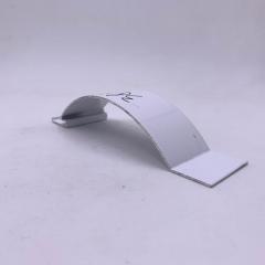
Think about what a finished mast section actually requires. The raw extrusion is just the starting point. You need precision cutting to length, CNC drilling for spreader brackets and fitting holes, possibly bending for boom sections, and surface treatment to protect against saltwater corrosion. A custom aluminum extrusion supplier who handles all of this under one roof delivers consistency that fragmented supply chains cannot match.
Evaluating supplier capability starts with understanding what equipment and processes matter for marine profiles. Press capacity determines what profiles a supplier can produce. Small presses (600-1800T) handle thin, precise profiles. Medium presses (2000-3500T) suit general industrial sections. Large presses (5000-10,000T) become necessary for heavy structural components with complex geometries.
For mast extrusions, you'll typically need medium to large press capacity depending on your section size. A supplier with multiple press capacities offers flexibility as your requirements evolve or production volumes change.
CNC machining capability matters just as much as extrusion capacity. Mast sections require precise hole patterns for hardware mounting, clean cuts to exact lengths, and sometimes complex machining for integrated fittings. Look for suppliers with in-house CNC machining centers capable of cutting, drilling, and bending to your specifications. Integration reduces transportation between subcontractors, prevents handling damage, and shortens overall lead time.
Surface treatment options deserve careful attention for marine applications. Anodizing is critical for saltwater service, but not all anodizing is equal. Check whether the supplier controls anodizing bath parameters like temperature, voltage, and acid concentration. Thickness verification matters too: standard anodizing runs 10-20 micrometers, while marine and architectural applications often specify 25 micrometers or more.
Shengxin Aluminium exemplifies the kind of full-service capability that simplifies aluminum mast extrusion sourcing. Their facility houses 35 extrusion presses ranging from 600T to 5500T, covering everything from precision small profiles to heavy structural sections. CNC machining centers handle downstream processing, while surface treatment options include anodizing in custom colors, powder coating, PVDF, and micro-arc oxidation. Their 6063 aluminum tube capability and custom profile processing services apply directly to mast and boom extrusion needs.
Technical support throughout the project lifecycle separates professional suppliers from simple traders. A capable partner provides design-for-manufacturability feedback on your drawings, suggests feasibility and cost optimization improvements, and shares inspection documentation before shipment. This proactive communication prevents problems rather than reacting after defects occur.
Choosing the right finish for anodized aluminum extrusion marine applications depends on your priorities: maximum corrosion protection, aesthetic flexibility, or long-term repairability. Each treatment option brings distinct advantages:
For most mast applications, anodizing remains the practical choice. It delivers the corrosion protection marine environments demand while maintaining the natural metallic appearance that sailors expect. Powder coating makes sense when color matching or branding requirements override the repairability advantages of anodizing.
Whatever finish you specify, confirm that your supplier can meet the required thickness and quality standards. Ask for coating adhesion test results (ASTM D3359) and thickness verification documentation. These details matter when your mast will spend years exposed to salt spray and UV radiation.
6061-T6 is the industry standard for production sailboat masts. It offers an optimal balance of tensile strength (310 MPa), excellent weldability for fitting repairs, good corrosion resistance when anodized, and favorable extrudability for complex hollow profiles. While 7075 provides higher strength, its poor corrosion resistance and weldability make it impractical for marine applications. 6063-T5 works for lower-load components like booms but lacks sufficient strength for primary mast sections.
Galvanic corrosion occurs when aluminum contacts dissimilar metals in the presence of moisture. Prevent it by using isolation tape between fitting bases and the mast surface, installing plastic or nylon washers under fastener heads, and applying dielectric grease to threads and contact surfaces. Be especially cautious with carbon fiber components, which are highly noble relative to aluminum and can accelerate corrosion at contact points. Annual inspections should check for white powdery deposits and pitting at hardware locations.
Ix and Iy are moment of inertia values that describe how a mast section resists bending. Ix measures resistance to athwartships (side-to-side) bending, while Iy measures resistance to fore-aft bending. For fractional rigs where forestay loads concentrate at the hounds, higher Iy values are essential. The ratio between Ix and Iy reveals whether a section is optimized for specific load directions. Oval sections show higher Iy relative to Ix, while round sections display nearly equal values.
Custom extrusion makes sense for OEM builders producing boats in volume, class-rule-specific requirements not available off-the-shelf, or racing programs seeking performance optimization. However, custom profiles require significant investment: die development takes several weeks, minimum order quantities typically range from 500-1000 kg, and lead times run 8-16 weeks. Suppliers like Shengxin Aluminium offer comprehensive services from die development through anodizing, with 35 presses ranging from 600T to 5500T for various profile complexities.
Anodizing remains the preferred choice for marine masts because it creates an integral oxide layer that cannot peel or chip, unlike paint or powder coating. Marine-grade anodizing typically produces 25-50 micrometer coatings. While powder coating offers more color options, damage can expose underlying aluminum to corrosion. PVDF provides exceptional weathering resistance for visible yacht components, and micro-arc oxidation creates extremely hard surfaces for high-abrasion areas like boom tracks.


 Интернет Сервис
 0086 136 3563 2360
 sales@sxalu.com
 +86 136 3563 2360
 русский
 English
 français
 Deutsch
 español
 português
 العربية
 ไทย
ไทย Việt
Việt Українська