
Ever tried to create a threaded hole in your T-slot frame only to end up with stripped threads or a crooked connection? You're not alone. Learning to drill and tap aluminum extrusion properly is one of those skills that separates frustrating weekend projects from professional-quality builds.
Whether you're constructing a machine enclosure, building a DIY 3D printer frame, or assembling industrial workstations, understanding how to create reliable threaded connections in aluminum profiles is essential. The good news? Once you grasp the fundamentals, you'll produce clean, strong threads consistently.
Aluminum extrusion isn't like drilling into steel or hardwood. This soft metal behaves differently under cutting tools, and ignoring these differences leads to the problems you've probably already experienced.
Here's what makes working with profiles like 80-20 aluminum unique:
According to GAP Engineering, drilling and tapping can be the most time-consuming part of any T-slot project, but with the right equipment and information, you can produce high-quality results every time.
Before diving into techniques, let's clarify what we're actually doing when we drill and tap aluminum extrusion:
Drilling creates the pilot hole, which is the foundation for everything that follows. The pilot hole diameter directly determines how your threads will form and how strong they'll be. Too small, and you'll break taps. Too large, and your threads won't have enough material engagement.
Tapping is the process of cutting internal threads into that pilot hole. An aluminum tap cuts helical grooves that allow bolts or screws to thread securely into the extrusion. The tap for aluminum must be designed to handle the material's tendency to gall and stick.
When working with aluminum threaded inserts or direct-tapped holes, understanding material behavior matters. As noted by Components for Industry, aluminum is generally softer than steel and brass alloys, making it potentially prone to thread stripping after repeated use. This is precisely why proper technique becomes so important.
The challenge many DIY 3D printer builders and hobbyists face is that forum advice often skips the "why" behind recommendations. You'll read "use a spiral point tap" without understanding what makes it better for aluminum, or "use cutting fluid" without knowing which types actually work.
This guide bridges that gap. In the sections ahead, you'll find specific drill bit and tap size charts, step-by-step processes, and troubleshooting solutions, all designed to help you create professional-quality threads in your aluminum extrusion projects. No more stripped holes. No more crooked connections. Just clean, reliable results.
Choosing the wrong drill bit or tap size is the fastest way to ruin a perfectly good aluminum extrusion. Too small a pilot hole breaks taps. Too large means weak threads that strip under load. Getting this right requires matching your thread size to the correct drill bit, and that's exactly what the charts below provide.
When you drill and tap aluminum extrusion, the pilot hole diameter determines your thread engagement percentage. Most applications target 65-75% thread engagement for aluminum, which provides a strong connection without excessive tapping force. Higher engagement percentages increase holding strength but require more torque and raise the risk of tap breakage.
Metric extrusions like the popular 2020 and 4040 profiles typically use M3, M4, M5, and M6 threads. These sizes align with the slot widths and wall thicknesses found in most European and Asian-manufactured T-slot systems.
Here's your reference for metric thread and drill combinations:
| Thread Size | Tap Drill Size (mm) | Major Diameter (mm) | Compatible Extrusion Series |
|---|---|---|---|
| M3 x 0.5 | 2.50 | 3.0 | 2020, 3030 |
| M4 x 0.7 | 3.30 | 4.0 | 2020, 3030, 4040 |
| M5 x 0.8 | 4.20 | 5.0 | 3030, 4040, 4545 |
| M6 x 1.0 | 5.00 | 6.0 | 4040, 4545, 6060 |
| M8 x 1.25 | 6.80 | 8.0 | 4545, 6060, 8080 |
Notice that the tap drill size isn't simply the thread diameter minus the pitch. According to AutoDrill's thread sizing reference, these drill sizes are calculated to achieve optimal thread engagement in softer materials like aluminum. For example, an M4 thread uses a 3.30mm drill bit, not a 3.0mm bit, which would result in excessive engagement and potential tap binding.
If you're working with metric measurements but need to convert, remember that 1.6mm to inches equals approximately 0.063 inches, which helps when sourcing drill bits from mixed-unit suppliers.
American-manufactured extrusions from brands like 8020 Inc. and similar 10 series profiles predominantly use imperial thread sizes. The 1/4-20 tap size is particularly common for 10 series extrusions because it provides an excellent balance between thread strength and the available wall thickness.
Understanding the correct 1/4-20 taps and matching drill bits prevents the frustration of stripped threads:
| Thread Size | Tap Drill (Number/Letter) | Tap Drill Decimal (in.) | Compatible Extrusion Series |
|---|---|---|---|
| 10-24 | #25 | 0.1495 | 10 Series, 15 Series |
| 10-32 | #21 | 0.159 | 10 Series, 15 Series |
| 1/4-20 | #7 | 0.201 | 10 Series, 15 Series, 25 Series |
| 1/4-28 | #3 | 0.213 | 15 Series, 25 Series |
| 5/16-18 | F | 0.257 | 15 Series, 25 Series, 40 Series |
| 3/8-16 | 5/16 | 0.3125 | 25 Series, 40 Series |
The data above is sourced from Microform Precision's tap drill chart for aluminum, which provides drill sizes specifically calculated for soft metals rather than steel.
When determining the hole for 1/4-20 tap operations, always use a #7 drill bit (0.201 inches). This creates the ideal pilot hole diameter for aluminum, giving you strong threads without excessive resistance during tapping. If you need a 1/2 inch to mm conversion for larger fastener calculations, that's 12.7mm, which helps when mixing imperial fasteners with metric extrusions.
For everyday workshop use, these are the tap size for 1/4-20 and other frequently needed combinations you'll reach for most often:
The correct pilot hole diameter is the single most important factor in thread quality. Always verify your drill bit size before starting, because the difference between a stripped thread and a perfect one often comes down to a few thousandths of an inch.
With your drill bit and tap combinations sorted, the next critical step is selecting the right tools to actually perform the operation. The quality of your taps and drilling equipment directly impacts whether those carefully sized holes produce clean, lasting threads.
Having the right drill bit and tap sizes means nothing if your tools can't deliver clean, precise cuts. When you drill and tap aluminum extrusion, the difference between professional results and frustrating failures often comes down to tool selection and quality. Cheap taps break. Wrong lubricants cause galling. Underpowered drills wander off-center.
Let's break down exactly what you need in your workshop to produce consistently excellent threads.
Your first decision involves how you'll drive the tap into the aluminum. Both approaches work, but each suits different situations.
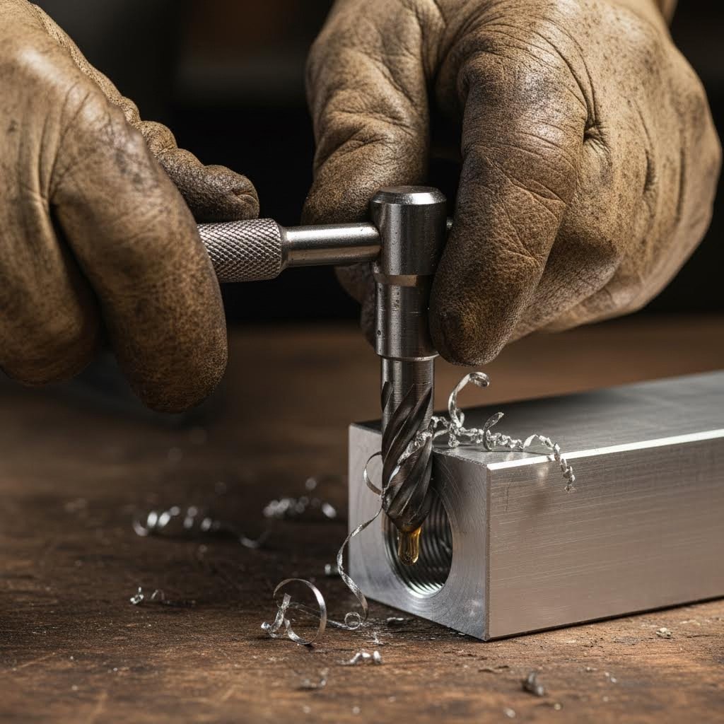
Hand tapping gives you direct tactile feedback. You feel when the tap bites into the material, sense resistance building, and know when chips need clearing. According to Yjing Extrusion's tapping guide, hand tapping offers more control and feel, which can be beneficial for delicate operations and is often preferred for small-scale or one-off projects.
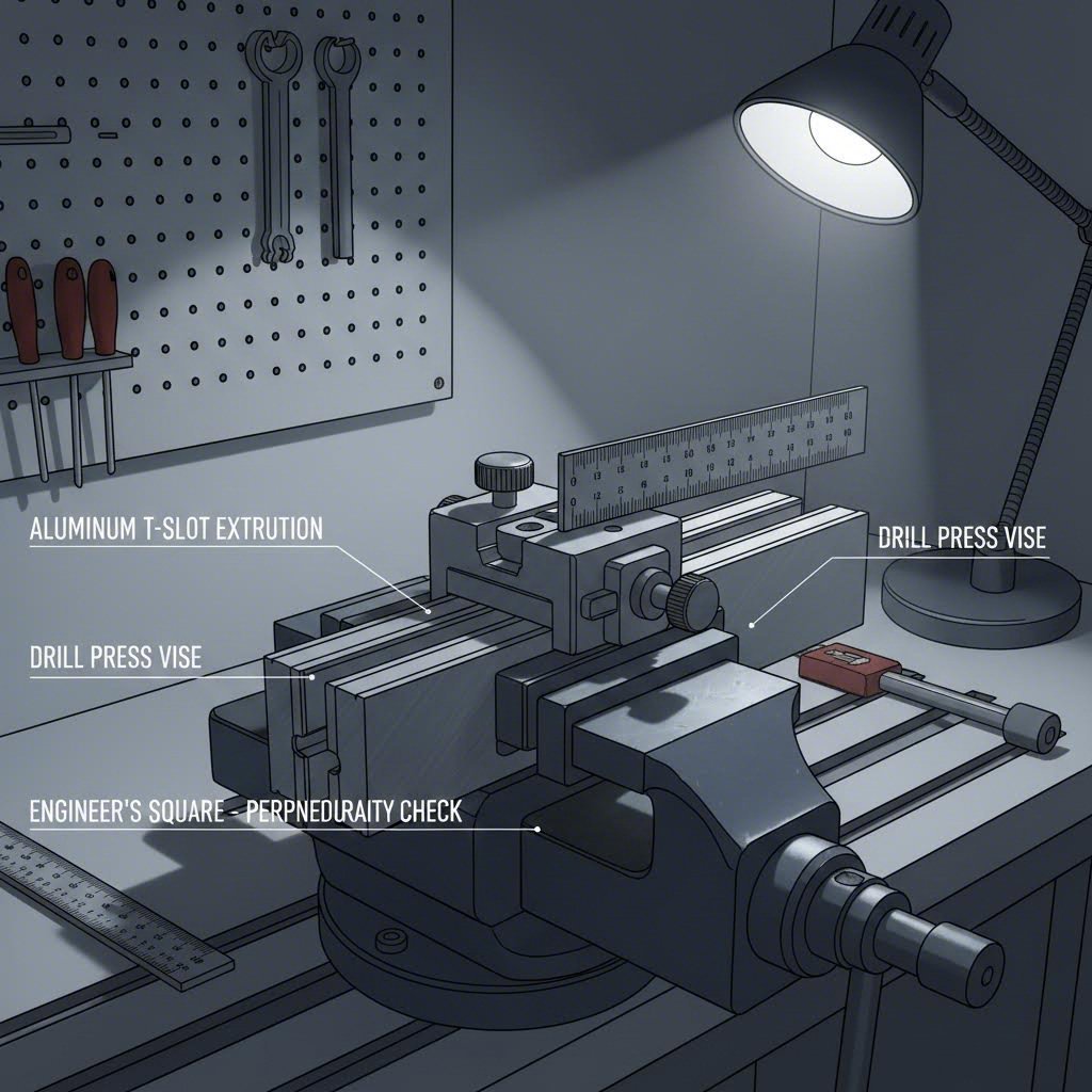
Machine tapping using a drill press or milling machine provides superior consistency and speed, especially when you're creating multiple identical holes. The machine maintains perfect perpendicularity throughout the operation, eliminating the human error that causes crooked threads.
When should you choose each method?
For most hobbyist and small-shop applications, hand tapping with a quality tap wrench delivers excellent results. Just remember that proper alignment techniques become critical when you remove the machine's built-in guidance.
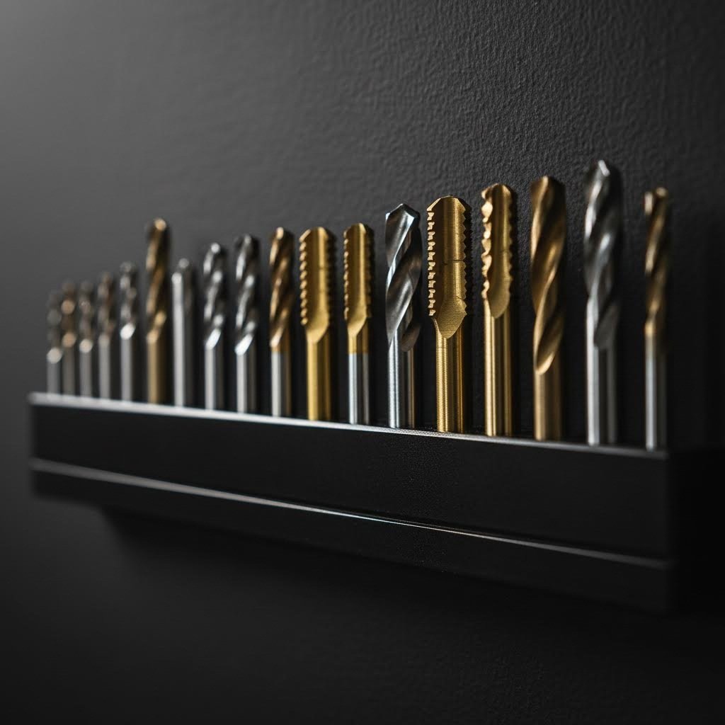
Not all taps perform equally in aluminum. The tap geometry dramatically affects chip evacuation, cutting force, and thread quality. Understanding your options helps you choose the right tool for each situation.
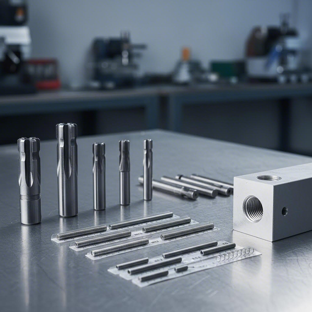
Sandvik Coromant's tap selection guide identifies four primary tap types: straight flute, spiral point, spiral flute, and forming taps. For aluminum extrusions, two types dominate:
Spiral point taps (also called gun taps) push chips forward, ahead of the cutting action. This design excels in through-holes because chips exit the far side rather than packing into the flutes. The forward chip ejection reduces binding and heat buildup, both common problems when working with aluminum's sticky chips.
Spiral flute taps pull chips backward, up and out of the hole. These work better for blind holes where chips have nowhere to go but back toward you. The helical flutes act like an auger, lifting material away from the cutting edges.
Here's when to use each type:
| Tap Type | Best Application | Chip Direction | Aluminum Performance |
|---|---|---|---|
| Spiral Point | Through holes | Forward (exits bottom) | Excellent - reduces galling |
| Spiral Flute | Blind holes | Backward (exits top) | Very good - clears chips from blind holes |
| Straight Flute | General purpose | Minimal evacuation | Acceptable - requires frequent backing out |
| Forming Tap | High-strength threads | No chips produced | Excellent - creates stronger threads |
Forming taps deserve special mention. Unlike cutting taps, they displace aluminum rather than removing it. According to Sandvik Coromant, forming taps often give longer tool life and produce up to 100% stronger threads with lower surface roughness. However, they require precise pilot hole diameters and excellent lubrication to work properly.
Skip the cutting fluid, and you'll understand why experienced machinists never do. Aluminum tends to weld itself to cutting tools when heat builds up, a phenomenon called galling. The result? Torn threads, stuck taps, and ruined workpieces.
But not all lubricants work for aluminum. Yjing Extrusion's guide emphasizes that aluminum-specific tapping fluids are formulated to prevent galling and chip welding. These specialized lubricants dissipate heat more effectively than general-purpose cutting oils designed for steel.
Avoid:
Use instead:
Before starting any drilling and tapping operation on aluminum extrusion, gather these essentials:
While these tools serve metalworking, the precision requirements parallel other workshop equipment. Just as a fabric cutting machine or cloth cutting machine demands sharp blades and proper technique for clean results, your tapping operation requires quality tooling matched to the material.
For production environments, combination drill-tap bits perform both operations in a single pass. These specialized tools drill the pilot hole and cut threads without a tool change.
Advantages include dramatically faster cycle times and guaranteed concentricity between hole and threads. However, they're less forgiving than separate operations and typically cost more per unit. For one-off projects, stick with separate drilling and tapping. For repetitive production work, combination bits save significant time.
The broken tap stuck in your extrusion started as a budget purchase. Quality tooling costs more upfront but prevents the frustration and wasted material that cheap tools cause.
For hobbyists, mid-range HSS taps from reputable tool suppliers deliver reliable performance without professional-grade prices. Industrial users should consider cobalt or carbide taps for extended life and consistent results across thousands of holes.
Where you source tools matters less than buying from suppliers who understand metalworking. General hardware stores often stock taps designed primarily for steel, which lack the geometry optimizations for aluminum's unique cutting characteristics.
With proper tools assembled, the next challenge becomes keeping your drill bit and tap perfectly perpendicular to the extrusion surface. Even the best equipment produces crooked threads when alignment fails.
You've selected the perfect tap, measured your pilot hole diameter twice, and applied premium cutting fluid. Then the drill bit wanders off-center, and suddenly your carefully planned connection sits at an angle. Sound familiar? Misalignment is the silent killer of otherwise perfect drilling and tapping operations, and it happens more often than most builders admit.
When you open a hole in aluminum extrusion freehand, even small angular errors compound into significant problems. A drill bit tilted just 2 degrees off perpendicular creates a visibly crooked thread that won't accept fasteners properly. The good news? T-slot extrusions actually provide built-in features that help solve this problem, if you know how to use them.
Here's something many DIY builders overlook: the T-slot running along your extrusion is machined with exceptional precision. Those slots maintain consistent width and depth across the entire profile length, making them ideal reference surfaces for alignment.
Think about it. The slot walls sit perfectly parallel to the extrusion's centerline. The slot floor maintains a consistent distance from the outer faces. These machined surfaces become your alignment allies when positioning drill guides or checking perpendicularity.
To leverage the T-slot for alignment:
According to GAP Engineering, when you need to drill a hole through the center of a T-slot aluminum profile for a standard connection, the drill needs to be exactly perpendicular to the profile. The best method involves clamping your material in a drill press, but when that's not available, a drill guide becomes essential.
Not everyone has access to a drill press, and sometimes you need to add holes to frames already installed on-site. This is where drill guides and simple jigs transform frustrating guesswork into reliable results.
A drill guide is a small device that clamps onto your extrusion profile and physically constrains the drill bit to travel in a straight line. The guide eliminates human error by making it mechanically impossible to drill at an angle.
GAP Engineering offers a clever solution: 3D-printed drill guides designed specifically for T-slot profiles. These guides use bearings to maintain smooth, straight drill bit travel while T-nuts secure the guide firmly to your extrusion. The design works for occasional light-duty work and proves especially useful when modifying frames already installed in workshops or factories.
For those building their own jigs, consider these approaches:
Understanding why freehand drilling produces crooked holes helps you avoid the problem. Several factors work against you when drilling without guidance:
Drill bit wander: The moment a drill bit contacts aluminum, it wants to skate across the surface rather than bite in. Without a center punch dimple or guide, the bit drifts before establishing the hole.
Human instability: Your hands naturally introduce small movements. What feels perfectly steady actually includes constant micro-adjustments that translate into angular errors.
Visual misperception: Judging perpendicularity by eye alone is surprisingly difficult. Most people consistently tilt toward their dominant side without realizing it.
Inadequate clamping: An extrusion that moves during drilling guarantees misalignment. Even slight workpiece shifting as the bit bites creates angled holes.
The solution involves addressing each factor: center punch to prevent wander, guides to eliminate instability, reference surfaces to correct visual errors, and solid clamping to prevent movement.
Before worrying about drill bit alignment, ensure your extrusion cannot move during the operation. Proper clamping seems basic, but inadequate workholding causes more alignment failures than poor drilling technique.
Effective clamping for T-slot extrusions:
Unlike nominal lumber sizes where a 2x4 measures differently than labeled, precision extrusions maintain their stated dimensions. However, this precision works against you if clamping pressure distorts the profile.
Before committing your tap to a drilled hole, verify that the pilot hole is actually perpendicular. Checking alignment takes seconds and prevents threading operations that produce angled, unusable holes.
Follow this step-by-step verification process:
If verification reveals misalignment, you have options. For slight errors in non-critical holes, proceed carefully. For significant problems, consider enlarging the hole with a reamer while applying corrective pressure, or accepting the loss and drilling a new hole in a different location.
A crooked pilot hole always produces a crooked thread. No amount of careful tapping compensates for misaligned drilling. Verify perpendicularity before picking up your tap wrench.
With your hole drilled straight and verified perpendicular, you're ready for the actual threading operation. The next section covers optimal drilling speeds and the chip-clearing techniques that prevent broken taps and torn threads.
You've gathered quality tools, selected correct drill bit and tap sizes, and verified your alignment setup. Now comes the moment of truth: actually cutting metal. The drilling and tapping process for aluminum extrusion follows specific rules that differ significantly from working with steel. Ignore these differences, and you'll join the frustrated builders wondering why their taps keep breaking.
Let's walk through the complete process from first contact to finished thread, explaining not just what to do, but why each step matters.
Here's something that surprises many newcomers: aluminum requires much higher drilling speeds than steel. Where you might drill steel at 80-110 surface feet per minute (SFM), aluminum alloys like the 6063 used in most extrusions perform best at 200-300 SFM according to Norseman Drill's feeds and speeds reference.
Why the dramatic difference? Aluminum's softness means lower speeds allow the material to push and deform rather than cut cleanly. Higher RPM creates the shearing action needed for clean chip formation. Too slow, and you get gummy, torn holes. Too fast without proper feed rate, and heat builds up causing galling.
Use this formula to calculate your target RPM:
RPM = (3.8197 / Drill Diameter in inches) x SFM
For example, drilling a #7 hole (0.201") for a 1/4-20 tap at 250 SFM:
RPM = (3.8197 / 0.201) x 250 = approximately 4,750 RPM
Most handheld drills max out around 2,500-3,000 RPM, which works acceptably for aluminum extrusion. A drill press or milling machine gives you access to the optimal speed range. If you're limited to slower speeds, compensate by reducing feed pressure and ensuring excellent lubrication.
Feed rates matter equally. Norseman Drill recommends feed rates of 0.002" to 0.006" per revolution for drill bits between 1/8" and 1/4" diameter. This translates to steady, moderate pressure that lets the bit cut rather than forcing it through the material. Many makers familiar with feeds and speeds calculator tools for CNC work apply similar principles when hand drilling.
Follow this sequence for clean, accurately sized pilot holes:
Users running pen plotter or bcnc setups for CNC drilling can program these retractions automatically using peck drilling cycles. For hand drilling, develop the habit of regular retraction to prevent chip packing.
Drilling creates the hole, but tapping creates the threads. This is where most failures occur. Broken taps, stripped threads, and galled surfaces typically trace back to one root cause: inadequate chip clearing.
When a tap cuts threads, it produces chips that must go somewhere. In aluminum, these chips tend to pack tightly into the tap's flutes rather than breaking free cleanly. Continued rotation compresses these packed chips until something gives, usually the tap itself, snapping inside your workpiece.
The solution is the "quarter turn forward, half turn back" technique that experienced machinists swear by:
According to Delicoil's hand tapping guide, this backing-out motion is essential: "After every full turn forward, back the tap out a quarter turn to break and clear the chips." The specific ratio varies slightly between sources, but the principle remains constant: regular reversal prevents the chip packing that breaks taps.
Every tapping guide mentions lubrication, but few explain why skipping it virtually guarantees problems in aluminum. The answer involves the chemistry and physics of aluminum cutting.
Aluminum has a strong tendency toward adhesive wear, commonly called galling. When aluminum contacts steel tooling under pressure and heat, microscopic welding occurs at the interface. Fresh aluminum surfaces are highly reactive and bond readily to the tap's cutting edges. Once buildup begins, it accelerates as rough, galled surfaces create more friction, more heat, and more adhesion.
Cutting fluid creates a barrier between the tap and workpiece that:
But here's the critical detail: not all cutting fluids work for aluminum. Oils formulated for steel often contain sulfur or chlorine additives that can stain aluminum and actually promote adhesion rather than prevent it.
Use aluminum-specific tapping fluids such as:
Avoid general-purpose cutting oils, motor oil, and WD-40 as primary lubricants. These either lack the film strength needed for threading or contain additives that harm aluminum surfaces.
Putting it all together, here's the full process from prepared hole to finished threads:
The difference between a stripped thread and a perfect one often comes down to patience. Rushing the tapping process, skipping chip-clearing reversals, or neglecting lubrication causes the failures that careful technique prevents.
Even with perfect technique, problems occasionally occur. The next section covers what to do when taps break, threads strip, or holes end up misaligned, turning potential disasters into recoverable situations.
Even experienced machinists face the occasional broken tap or stripped thread. When you drill and tap aluminum extrusion regularly, these failures aren't a matter of if but when. The real question becomes: do you know how to recover, or does one mistake ruin your entire workpiece?
Understanding why failures occur helps you prevent them. Knowing how to fix them saves expensive extrusions from the scrap bin. Let's address the problems that actually frustrate builders in maker communities and provide solutions that work.
A tap snapped flush with the surface. Your stomach drops. That hardened steel fragment sits wedged inside your aluminum, seemingly impossible to remove without destroying the surrounding material. Before you reach for a hammer in frustration, know that several proven extraction methods exist.
According to Top Level CNC's machining guide, you have two choices when a tap breaks: find a way to remove it, or scrap the part. For small bespoke parts, scrapping might be acceptable. But for expensive aluminum extrusions already incorporated into a frame, extraction becomes essential.
Here are the most effective extraction methods for aluminum extrusions:
What doesn't work well? Drilling out the broken tap rarely succeeds because the tap's hardened steel destroys standard drill bits. You'd need carbide tooling and exceptional precision to avoid damaging the threads you're trying to save.
Sometimes threads strip despite your best efforts. Maybe someone over-torqued a bolt. Perhaps the original threads were cut with too large a pilot hole. Or repeated assembly cycles finally wore through the soft aluminum. Regardless of cause, the hole now won't hold fasteners securely.
Thread repair inserts solve this problem permanently. According to E-Z LOK's thread repair guide, helical coil inserts are ideal for stripped thread repair and reinforcement in softer metals like aluminum. Made from corrosion-resistant stainless steel, these inserts create threads stronger than the original aluminum.
The repair process follows these steps:
Helicoil-style inserts work particularly well because they distribute load across more material than the original threads. Just as actual lumber sizes differ from nominal measurements in woodworking, the insert's outer threads engage more aluminum than the original fastener would have, creating a stronger connection.
Before repairing stripped threads, understand why they failed. Otherwise, you'll repeat the same mistake. According to E-Z LOK, stripped bolt threads generally occur over time as metal fastenings wear out and loosen, creating potentially unsafe operating conditions.
Common causes include:
This table consolidates common failures with their likely causes and proven solutions:
| Problem | Likely Cause | Solution |
|---|---|---|
| Tap breaks during threading | Insufficient chip clearing, wrong tap type, no lubrication | Extract with tap extractor or EDM; prevent by using quarter-turn-back technique |
| Threads strip immediately | Pilot hole too large, wrong thread pitch | Install thread repair insert; verify drill/tap sizing chart |
| Threads strip under load | Insufficient engagement depth, over-torquing | Use longer engagement or inserts; apply aluminum-appropriate torque values |
| Threads strip over time | Vibration loosening, repeated assembly cycles | Use thread-locking compound; install helicoil for permanent repair |
| Galled, torn threads | No cutting fluid, wrong lubricant type | Chase threads with 10 tap or 20 tap; prevent with aluminum-specific fluid |
| Crooked threads | Misaligned pilot hole, tap started at angle | Ream hole larger and use insert; use drill guide for future holes |
| Fastener won't thread fully | Chips packed in blind hole, insufficient depth | Clean thoroughly; tap deeper if wall thickness allows |
The best repair is the one you never need to make. These prevention strategies address root causes rather than symptoms:
Calculate proper thread engagement depth: Standard practice calls for thread engagement of 1.5 to 2 times the fastener diameter in aluminum. A 1/4-20 bolt needs 0.375" to 0.500" of thread engagement for full strength. Shorter engagement works for light loads but fails under stress.
Use correct torque values: Aluminum threads require significantly lower torque than steel. A 1/4-20 bolt in aluminum typically needs only 4-6 ft-lbs, compared to 8-10 ft-lbs in steel. When in doubt, use a torque wrench rather than guessing.
Apply thread-locking compound for vibration resistance: Blue Loctite or similar medium-strength compounds prevent loosening without making future disassembly impossible.
Avoid repeated assembly cycles when possible: Each time you remove and reinstall a fastener, threads wear slightly. Design connections for minimal disassembly, or use threaded inserts from the start in locations requiring frequent access.
Inspect threads before assembly: A quick visual check catches damaged threads before they fail under load. Chasing threads with a tap removes minor burrs and debris that accelerate wear.
Most threading failures trace back to rushing the process or skipping fundamentals. Proper pilot hole size, adequate lubrication, correct chip clearing, and appropriate torque values prevent the vast majority of problems builders encounter.
Understanding failure modes and repairs gives you confidence to tackle any threading project. But some applications demand precision beyond what field work can deliver. The next section explores advanced techniques for complex applications, including thread depth calculations and working with anodized surfaces.
You've mastered the fundamentals. Your pilot holes are straight, your chip-clearing rhythm is second nature, and stripped threads have become rare exceptions rather than frustrating norms. Now it's time to elevate your skills beyond basic drilling and tapping into territory that separates hobbyist work from professional-grade results.
Advanced applications demand deeper understanding. How deep should threads actually engage for maximum strength? What happens when you tap through that hard anodized coating? Should you machine first and anodize later, or the reverse? These questions matter when you're building precision equipment like a dual extruder 3D printer frame or industrial automation systems where failure isn't an option.
Thread engagement depth directly determines connection strength. Too shallow, and threads strip under load. Too deep, and you risk breaking through thin extrusion walls or wasting time cutting threads that add no benefit.
According to KATO Fastening's technical guide, the minimum full thread tapping depth (H) for both through and blind holes equals the insert nominal length plus one thread pitch. For example, a 1/2-20 thread with a 0.500" insert length requires: H = 0.500 + 0.050 = 0.550" minimum tapping depth.
But what about direct-tapped holes without inserts? The general rule for aluminum is:
Minimum Thread Engagement = 1.5 x Fastener Diameter
Optimal Thread Engagement = 2.0 x Fastener Diameter
For a 1/4-20 bolt (0.250" diameter), this means:
Here's where extrusion wall thickness becomes critical. Most T-slot profiles have walls between 1.5mm and 4mm thick depending on the series. A 2020 profile might offer only 2mm of material for threading, while a heavy-duty 4080 provides substantially more. Always verify your extrusion's cross-section drawing before planning thread depths.
When wall thickness limits your engagement depth, consider these alternatives:
The distinction between blind and through-hole tapping affects everything from tap selection to depth calculations. Understanding these differences prevents the mistakes that plague complex assemblies.
Through-holes extend completely through the material. Chips can exit either direction, spiral point taps push debris forward and out, and thread depth isn't constrained by material thickness. These are the easier application.
Blind holes end inside the material. Chips must exit backward against cutting direction, requiring spiral flute taps. More critically, you must account for the tap's chamfer, which contains partial threads that don't provide full engagement.
According to KATO's drilling and tapping depth reference, plug-style taps have a 4-pitch thread chamfer, while bottoming taps have a 2-pitch chamfer. These partial threads must be accommodated at the blind hole's bottom.
For blind hole depth calculations:
Minimum Drill Depth = Thread Engagement + Tap Chamfer + Clearance
Using their example of a 1/2-20 x 0.500" thread with a plug tap:
Minimum drill depth = 0.475 (assembled insert length) + 1.5 x 0.050 (setdown) + 4 x 0.050 (tap chamfer) + 1 x 0.050 (clearance) = 0.775"
This means your drilled hole must extend significantly deeper than the actual thread engagement you need. Failing to account for chamfer length results in incomplete threads at the critical bottom portion of the hole.
Anodized aluminum presents a unique challenge. That beautiful, protective oxide layer is significantly harder than the underlying aluminum, creating a two-material cutting situation that can chip, crack, or produce rough thread starts.
Arbiser Machine's design guide explains the core problem: anodizing creates coating buildup of 0.0006" to 0.0008" on threaded surfaces. For threads smaller than 1/4-20, this buildup can exceed the tolerance range of the part itself, making it impossible for fasteners to thread properly.
You have two primary approaches:
Tap before anodizing: Machine all threads in raw aluminum, then send the part for anodizing. The oxide layer forms over the threads, potentially requiring slight oversizing to accommodate buildup. This approach works well for larger threads (1/4-20 and above) where the tolerance range accommodates the coating thickness.
Mask and tap after anodizing: For threads that must remain uncoated, the anodizer masks the hole locations during processing. You then tap into raw aluminum surrounded by the anodized surface. According to Arbiser Machine, this is the only guaranteed solution for threads smaller than 1/4-20.
When tapping through existing anodized surfaces:
Not all aluminum machines identically. While 6063 dominates the extrusion market, understanding alloy differences helps when working with specialized profiles or machined components.
Key considerations for common extrusion alloys:
The T-number indicates temper condition. T5 means artificially aged after extrusion; T6 means solution heat-treated and artificially aged, producing higher strength. Both tap similarly, though T6 may feel slightly more resistant during cutting.
Builders working on precision projects like types of 3D printers requiring tight tolerances should verify their extrusion alloy and temper. While the differences are subtle for basic connections, they matter for demanding applications.
Your extrusion's cross-section determines what's physically possible. Before planning any threaded connection, obtain the manufacturer's profile drawing showing wall thicknesses at potential drilling locations.
Consider these relationships:
| Extrusion Series | Typical Wall Thickness | Maximum Practical Thread | Recommended Approach |
|---|---|---|---|
| 2020 | 1.5-2.0mm | M4/10-24 | Through-bolt or inserts for larger fasteners |
| 3030 | 2.0-2.5mm | M5/1/4-20 | Direct tapping feasible for most applications |
| 4040 | 2.5-3.5mm | M6/5/16-18 | Good engagement for standard hardware |
| 4080/4545 | 3.0-4.0mm | M8/3/8-16 | Excellent for heavy-duty connections |
When wall thickness limits direct tapping, through-hole designs with T-nuts or drop-in fasteners often provide superior holding power compared to marginal thread engagement in thin material.
Advanced technique isn't about complexity for its own sake. It's about understanding your materials and constraints well enough to choose the right approach for each specific application.
These professional-grade considerations help you push beyond basic assemblies into precision work. However, some projects demand capabilities that exceed workshop equipment. When tolerances tighten or quantities increase, understanding when professional processing makes sense becomes its own valuable skill.
You've developed solid drilling and tapping skills. Your threads are clean, your alignment is consistent, and broken taps have become rare occurrences. But here's a question worth asking: should you actually be doing this work yourself?
Sometimes the answer is clearly yes. Other times, the math, precision requirements, or production volumes make professional processing the smarter choice. Knowing when to drill and tap aluminum extrusion yourself versus when to outsource separates efficient builders from those burning hours on work better handled by specialists.
The decision isn't simply about capability. It's about matching your approach to your project's actual requirements. Consider what you're building, how many you need, and what tolerances matter.
DIY tapping makes sense when:
Professional processing becomes advantageous when:
According to Parco Inc.'s T-slot guide, the assembly process for quality T-slot systems is straightforward and doesn't require expensive, specialized tools. This accessibility makes DIY work viable for many projects. However, the same modularity that enables easy assembly also creates demand for precision-machined components when projects scale beyond workshop production.
The economics shift dramatically once volume enters the picture. Hand-tapping ten holes takes the same time per hole as tapping one hundred. CNC machining, however, becomes progressively cheaper per unit as quantities increase.
According to industry cost analysis, single-piece machining usually comes with higher cost because upfront steps like machine setup and tool adjustments cannot be spread across multiple parts. When production volume increases, these setup costs are averaged out, reducing per-unit aluminum CNC machining cost significantly.
Consider the true cost comparison:
| Factor | DIY Tapping (10 pieces) | Professional CNC (10 pieces) | Professional CNC (100 pieces) |
|---|---|---|---|
| Setup cost per piece | None | High (amortized over few units) | Low (spread across volume) |
| Labor time per hole | 5-10 minutes | Seconds | Seconds |
| Consistency | Variable | Excellent | Excellent |
| Scrap rate | Higher (learning curve) | Minimal | Minimal |
| Total cost advantage | Usually lower | Often higher | Usually lower |
The crossover point varies by complexity and your local labor rates, but typically falls between 15-30 pieces for simple drilling operations. Complex machining with multiple operations shifts that crossover lower.
Beyond cost considerations, CNC machining delivers capabilities that manual work simply cannot match. Five-axis CNC equipment can produce complex geometries, precise angular holes, and tight-tolerance features that would be impossible to achieve consistently by hand.
As noted by Precision Steel Services, 5-axis CNC equipment expedites fabrication of custom extrusions without increasing costs. The technology handles design features that competing fabrication approaches may need to outsource, including counterbores, pockets, slots, and precisely located mounting patterns.
When evaluating professional processing partners, look for:
For builders considering professional processing, suppliers like Shengxin Aluminium offer deep processing services backed by over 30 years of experience with 6063 aluminum extrusions. Their CNC machining centers handle precise cutting, drilling, and bending operations, while integrated surface treatments including anodizing and powder coating eliminate the need to coordinate multiple vendors. This end-to-end capability from die development to mass production proves particularly valuable for scaled projects requiring consistent quality across hundreds or thousands of pieces.
The decision framework comes down to honest assessment of your specific situation. Ask yourself:
For tnutz extrusion frames supporting a home workshop project, hand-tapping remains perfectly appropriate. For production equipment requiring 1/4 x 20 tap holes positioned within thousandths of an inch across fifty assemblies, professional CNC processing delivers better results at competitive cost.
The 80-20 hardware ecosystem thrives precisely because both approaches coexist. DIY capability enables prototyping and customization. Professional processing enables production and precision. Understanding when each applies maximizes both your results and your resources.
The best builders know their limits. Sometimes that means developing new skills. Other times it means recognizing when specialists deliver superior results more efficiently than self-performed work ever could.
Whether you're tapping threads yourself or specifying machined extrusions, the fundamentals covered throughout this guide apply. Correct hole sizes, proper technique, and quality tooling matter regardless of who performs the work. The final section consolidates these essentials into quick-reference guidance for your workshop.
You've now walked through everything from fundamental concepts to advanced techniques and professional processing options. Whether you're building an automated bike rack for your garage or assembling precision equipment, the principles remain consistent. Clean threads come from correct preparation, proper technique, and patience.
Let's consolidate what matters most into actionable guidance you can reference during your next project.
Print this section and post it near your drill press. These essentials prevent the mistakes that ruin workpieces:
The quarter-turn forward, half-turn back rhythm prevents more broken taps than any expensive tool ever will. Never skip chip clearing, and never skip lubrication.
Resources like the instructable website and various instructables projects demonstrate these techniques in action. Watching experienced makers apply these principles reinforces what reading alone cannot fully convey.
Here's advice that separates successful builders from frustrated ones: practice on scrap before touching your final workpiece.
Find offcuts from previous projects or purchase a short length of inexpensive extrusion specifically for practice. Drill holes. Tap threads. Intentionally make mistakes to learn how problems develop. Strip a thread on purpose to understand what over-torquing feels like. Break a cheap tap to recognize the warning signs before failure.
This low-stakes experimentation builds the tactile knowledge that guides your hands during real work. You'll recognize when chips need clearing, feel when alignment drifts, and sense when threads are cutting cleanly versus tearing.
Proper technique with modest tools outperforms poor technique with expensive equipment every time. Master the fundamentals before investing in premium tooling.
For projects requiring precision beyond workshop capability or quantities that justify professional processing, integrated suppliers streamline the path from concept to completion. Shengxin Aluminium's custom extrusion services combine CNC machining with surface treatments like anodizing and powder coating, delivering finished components ready for assembly. Their 30+ years of experience with 6063 aluminum means your specifications translate into consistent results across production volumes.
Whether you tap every thread yourself or specify factory-machined profiles, the knowledge you've gained ensures better outcomes. You understand why pilot hole diameter matters, how chip clearing prevents failures, and when professional processing makes sense. That understanding transforms aluminum extrusion from frustrating material into reliable building blocks for whatever you imagine next.
Yes, almost any quality drill can handle aluminum extrusion since aluminum is a relatively soft metal. For precise assemblies, a drill press provides better results than handheld drills. Use higher RPM speeds (200-300 SFM) compared to steel, apply aluminum-specific cutting fluid, and retract periodically to clear chips. Center punch your mark first to prevent bit wander, and always verify your pilot hole size matches your intended tap requirements.
Absolutely. Aluminum's relative softness makes it easier to machine than steel, allowing for faster drilling speeds and deeper cuts. The key is using proper technique: correct pilot hole diameter based on thread size, aluminum-specific taps (spiral point for through-holes, spiral flute for blind holes), and always using cutting fluid formulated for aluminum. The quarter-turn forward, half-turn back tapping rhythm prevents chip packing and broken taps.
Drill aluminum at moderate to high speeds, significantly faster than steel. Recommended surface speeds are 200-300 SFM for aluminum versus 80-110 SFM for steel. Too slow allows the material to push and deform rather than cut cleanly, creating gummy, torn holes. Apply constant but moderate pressure while drilling, and use aluminum-specific cutting fluid to prevent heat buildup and galling.
Use a #7 drill bit (0.201 inches) for 1/4-20 taps in aluminum extrusion. This size creates optimal thread engagement of 65-75% without excessive tapping resistance. The 1/4-20 thread is the most common choice for 10 series and 15 series extrusions like 80/20 profiles, providing excellent balance between thread strength and available wall thickness.
Thread repair inserts like helicoils provide a permanent solution for stripped threads. Drill out the damaged threads using the insert kit's specified drill size, tap new larger threads for the insert's outer diameter, then install the helical coil using the provided tool. The stainless steel insert creates threads stronger than the original aluminum. For prevention, ensure proper thread engagement depth (1.5-2x fastener diameter) and use aluminum-appropriate torque values.


 Интернет Сервис
 0086 136 3563 2360
 sales@sxalu.com
 +86 136 3563 2360
 русский
 English
 français
 Deutsch
 español
 português
 العربية
 ไทย
ไทย Việt
Việt Українська