Imagine you've just sealed up a new-build home with triple-glazed windows, insulated walls, and airtight membranes. The energy performance is outstanding, but within weeks the occupants notice streaming condensation on windows, musty smells in bathrooms, and a persistent stuffiness that no amount of opening the back door seems to fix. The culprit? A ventilation strategy that was either missing or poorly specified. This is exactly the scenario that Approved Document F exists to prevent.
Approved Document F is the statutory guidance published by the UK government that explains how to meet the ventilation requirements set out in Part F of Schedule 1 to the Building Regulations 2010. In plain terms, it tells architects, builders, and specifiers how to provide adequate fresh air to buildings in England so that occupants stay healthy and building fabric stays protected.
The document covers minimum ventilation provisions designed to control three key threats to indoor air quality:
It applies to both new and existing dwellings, as well as non-domestic buildings such as offices, schools, and retail premises. The guidance is split into two volumes: Volume 1 addresses dwellings, while Volume 2 covers buildings other than dwellings. Each volume contains detailed specifications for ventilation rates, system types, and commissioning procedures tailored to its building category.
Here's a distinction that trips up even experienced professionals. The building regulations approved document F is not the law itself. The legal requirement comes from Part F of Schedule 1 to the Building Regulations 2010, which states the functional requirement in deliberately broad language:
F1.—(1) There shall be adequate means of ventilation provided for people in the building. (2) Fixed systems for mechanical ventilation and any associated controls must be commissioned by testing and adjusting as necessary to secure that the objective referred to in sub-paragraph (1) is met.
That's it. The regulation doesn't tell you how many litres per second your kitchen extract fan must deliver or whether you need trickle vents in your bedroom windows. Those specifics live in Approved Document F, which provides one accepted way of satisfying Requirement F1. You'll notice the key word here is "one" way. Alternative approaches are entirely permissible provided they demonstrate compliance with the functional requirement. A designer could, for example, use computational fluid dynamics modelling or manufacturer-specific performance data to justify a ventilation strategy that departs from the prescriptive tables in the approved document, as long as it delivers adequate ventilation for occupants.
This flexibility matters because building designs vary enormously. A converted Victorian terrace presents different ventilation challenges than a modern apartment block, and approved document part f recognises that a one-size-fits-all prescription would be impractical. The guidance offers a safe harbour: follow it, and you can presume compliance. Deviate from it, and the burden shifts to you to prove your alternative works just as well.
What makes this document especially relevant right now is the tightening relationship between energy efficiency and ventilation. As buildings become more airtight to meet conservation of fuel and power targets, the old reliance on draughts and air leakage to ventilate spaces simply disappears. Controlled, planned ventilation becomes essential rather than optional. Getting the approved document f building regulations requirements right at the design stage is far cheaper and simpler than retrofitting solutions after building control flags a problem on site.
Understanding how ventilation standards reached their current form reveals why specific rates and system types are prescribed the way they are, and why the latest edition introduced changes that caught many builders off guard.
Ventilation guidance in England didn't appear overnight as a fully formed rulebook. It grew through decades of real-world experience, scientific research, and hard lessons learned from buildings that made people ill. Each edition of Approved Document F responded to a specific problem: homes getting tighter, occupants getting sicker, or the science revealing hazards that earlier drafts simply hadn't anticipated.
The Planning Portal's archive of previous editions traces a clear trajectory. The 1995 edition laid much of the foundational framework still recognisable today, establishing the concept of background ventilation through trickle vents and intermittent extract in wet rooms. It was amended in 2000, but the core structure remained relatively modest in its demands because buildings of that era were, frankly, quite leaky. Air infiltration through gaps around windows, doors, and service penetrations provided a de facto ventilation rate that the regulations could afford to overlook.
The 2006 edition sharpened the requirements. By this point, energy efficiency regulations were pushing envelope airtightness upward, and evidence was mounting that relying on uncontrolled air leakage was neither reliable nor healthy. The approved document f ventilation 2010 edition then consolidated these improvements further, aligning the guidance with the restructured Building Regulations 2010. This edition introduced clearer performance benchmarks and addressed the growing variety of mechanical ventilation options available to designers.
A pivotal update came with the approved document f - ventilation 2013 edition amendments, which were used from 6 April 2013 alongside the approved document part f 2010 text. These amendments refined specific provisions without overhauling the entire document, reflecting incremental improvements in understanding how dwellings actually perform once occupied.
The most significant overhaul arrived on 15 June 2022. The building regulations approved document f ventilation 2010 edition was replaced entirely by two new volumes, introduced under The Building Regulations etc. (Amendment) (England) Regulations 2021. For the first time, dwellings and non-domestic buildings received dedicated, separate guidance documents. Crucially, this edition launched alongside the brand-new Approved Document O (Overheating), acknowledging that ventilation and overheating risk are inseparable design considerations in modern, well-insulated buildings.
| Edition | Key Changes | Primary Driver |
|---|---|---|
| 1995 (amended 2000) | Established background ventilation via trickle vents; intermittent extract in wet rooms | Foundational indoor air quality framework |
| 2006 | Tightened provisions for extract rates; greater recognition of mechanical ventilation systems | Rising airtightness standards under energy efficiency regulations |
| 2010 (incorporating further amendments) | Aligned with Building Regulations 2010 structure; clearer performance benchmarks | Regulatory restructuring and continued airtightness improvements |
| 2013 amendments (to 2010 edition) | Refined specific provisions; updated cross-references | Incremental evidence on occupied building performance |
| 2022 (current, from 15 June 2022) | Split into Volume 1 (dwellings) and Volume 2 (non-domestic); introduced alongside Approved Document O | Modern airtightness levels; overheating risk; updated IAQ science |
Why did each revision tighten the rules? The answer lies in how buildings trap pollutants when envelope performance improves. Research published in Sustainability demonstrates that energy retrofits focused on improving thermal performance consistently increase indoor CO₂ concentrations because the uncontrolled air pathways that once diluted pollutants are sealed shut. Indoor air can be up to five times more polluted than outdoor air when ventilation is inadequate, a finding that has driven regulators to raise minimum airflow rates with each successive edition.
Consider what happens inside a typical home. A family of four generates substantial moisture through cooking, bathing, showering, and drying clothes. Without adequate extract ventilation in kitchens and bathrooms, that moisture condenses on cold surfaces, promoting mould growth and degrading building fabric. Meanwhile, CO₂ from respiration accumulates in bedrooms overnight. Concentrations above 1,000 ppm are linked to drowsiness and impaired cognitive function, while sustained levels above 2,000 ppm can cause nausea and increased heart rate.
The approved document part f building regulations 2010 framework addressed these issues by prescribing both whole-dwelling ventilation rates and room-specific extract rates. Whole-dwelling rates target the continuous dilution of CO₂ and background pollutants like volatile organic compounds (VOCs) from furnishings and cleaning products. Room-specific extract rates tackle the intense, localised moisture and odour spikes that occur when someone runs a shower or fries an egg. Each edition has progressively refined these dual requirements as the science has matured.
This parallel evolution of airtightness and ventilation standards creates a practical question every project team must answer: which ventilation system fits their specific building? The answer depends on whether you're working on a dwelling or a commercial premises, and whether the project is new construction or an intervention in an existing building.
That question of whether you're dealing with a home or a commercial premises isn't academic. Since 15 June 2022, Approved Document F ventilation guidance in England has been split into two entirely separate publications, each with its own scope, requirements, and compliance approaches. Pick the wrong volume, and you're designing to the wrong standard from day one.
Approved Document F Volume 1 applies to dwellings, covering houses, flats, maisonettes, and rooms used for residential purposes. Its reach, however, extends well beyond new-build projects. Volume 1 also governs existing dwellings undergoing material alterations, a change of use, or renovation work that affects ventilation provision. This is the detail that catches many contractors off guard.
Imagine you're replacing windows in a 1990s semi-detached home. The original windows had no trickle vents because the regulations at the time didn't require them. Under the current approved document f volume 1, those replacement windows must include background ventilators that meet minimum equivalent area requirements, or an alternative wall-mounted ventilator must be provided. The government's own FAQ is unambiguous on this point: a homeowner cannot sign a disclaimer opting out of background ventilation, and a night-latch position on a window does not qualify as a compliant solution. The work must satisfy Part F in full before it can be certified.
For new dwellings, the requirements are more comprehensive. Designers must specify a complete ventilation strategy covering whole-dwelling background ventilation, room-specific extract ventilation in wet rooms, and purge ventilation for rapid air changes. The approved document f ventilation 2021 dwellings pdf lays out four recognised ventilation systems for achieving these goals, each with detailed airflow specifications and installation guidance.
Approved Document F Volume 2 addresses buildings other than dwellings: offices, retail premises, schools, healthcare facilities, hospitality venues, and industrial buildings, among others. The ventilation challenges in these spaces differ fundamentally from domestic settings. Occupancy patterns are less predictable, internal heat gains from equipment and lighting are often substantial, and the range of pollutants can include chemicals, fumes, and biological contaminants specific to the building's function.
Volume 2 places greater emphasis on mechanical ventilation design, air handling unit specification, and ductwork sizing. Natural ventilation remains an option for some non-domestic building types, but the compliance calculations are more complex, typically requiring professional engineering input. Commissioning requirements are also more demanding, reflecting the greater system complexity involved.
It's worth noting that this two-volume structure applies specifically to England. Wales publishes its own approved document F Wales edition through the Welsh Government, which follows a similar two-volume format but operates under separate Welsh building regulations and its own transitional timeline.
Within Volume 1, the gap between new-build and existing-dwelling requirements is one of the most misunderstood aspects of the guidance. For a new dwelling, you're designing a ventilation system from scratch: selecting one of four recognised system types, calculating airflow rates for every habitable room and wet room, and coordinating with airtightness targets. The designer has full control over the building envelope and can optimise vent positions, duct runs, and fan locations from the outset.
Existing dwellings present a different challenge. The regulation here centres on a principle of non-degradation: any building work must not make the existing ventilation provision less satisfactory than it was before. If you strip out old windows that had trickle vents, the replacements must provide at least the same equivalent area of background ventilation. If the original windows had no trickle vents at all, you'll still need to install background ventilators in the new windows to meet current minimum standards, unless an existing wall ventilator in the same room already provides adequate airflow.
| Dimension | Volume 1 – Dwellings | Volume 2 – Non-Domestic Buildings |
|---|---|---|
| Scope | New and existing dwellings (houses, flats, maisonettes) | Offices, schools, retail, healthcare, hospitality, industrial premises |
| Triggers for compliance | New build, material alteration, change of use, window replacement, renovation | New build, material alteration, change of use, extensions, refurbishment |
| Key ventilation strategies | Four recognised systems (natural, cMEV, cMSV, MVHR); trickle vents for background ventilation | Mechanical ventilation design predominant; natural ventilation possible for simpler building types |
| Typical compliance approach | Prescriptive tables for airflow rates by room type and dwelling size | Engineering calculations; professional HVAC design; reference to CIBSE guidance |
| Commissioning emphasis | Mechanical systems must be commissioned; natural systems require installer confirmation of vent specification | Comprehensive commissioning and testing of air handling systems, ductwork, and controls |
This structural split between volumes and between new-build and existing-dwelling obligations shapes every practical decision on a project. Yet the most consequential choice for domestic construction comes one step earlier: selecting which of the four ventilation systems recognised by the guidance actually fits the building you're designing or renovating.
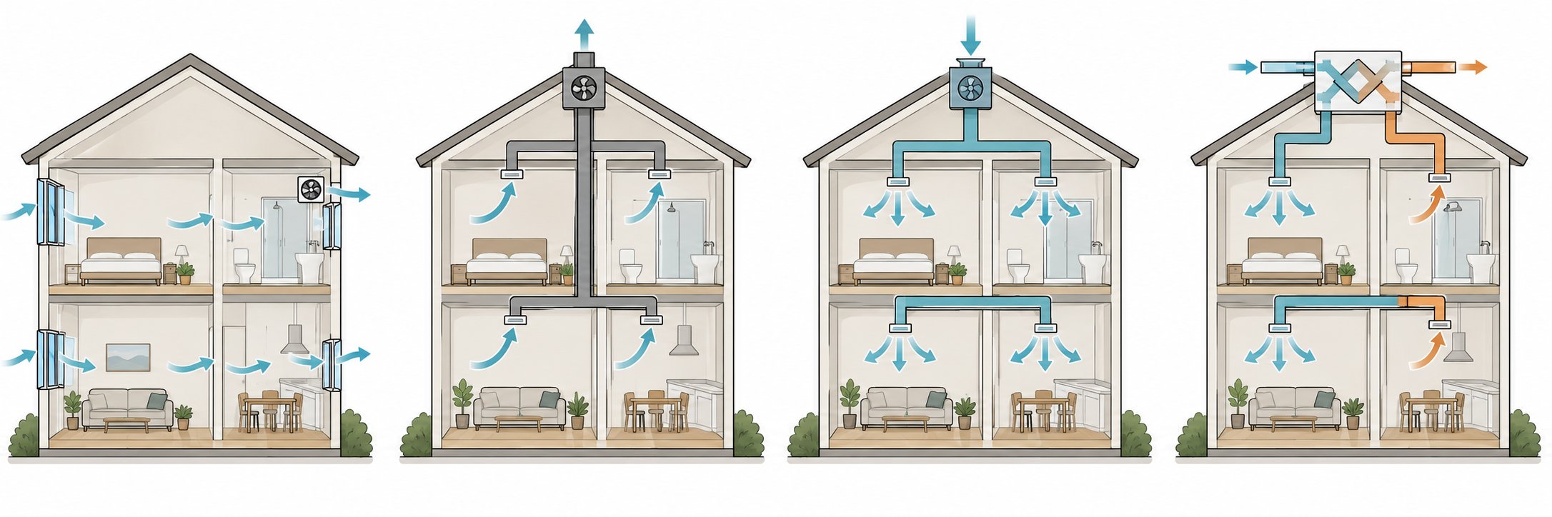
Picking a ventilation system isn't like choosing a paint colour. The choice you make determines ductwork routes, window specifications, energy performance calculations, and ultimately whether building control signs off your project. The building regulations approved document f means of ventilation guidance for dwellings recognises four distinct systems, each suited to different building types, budgets, and airtightness levels. Getting the match right at the design stage avoids costly rework later.
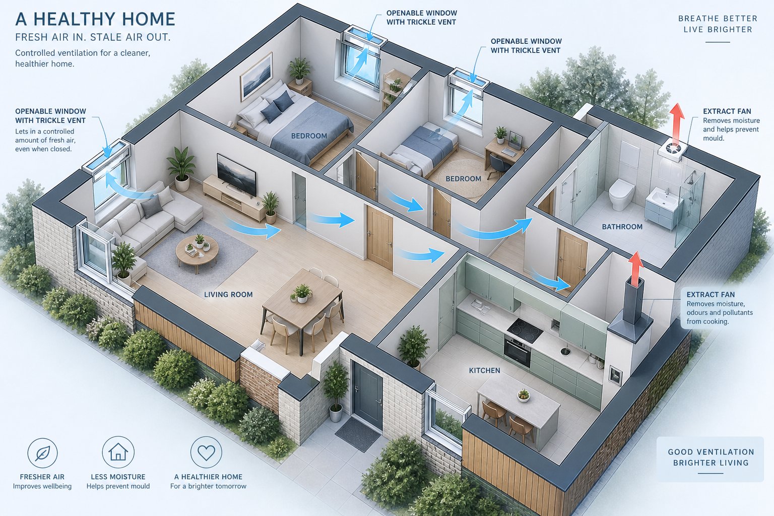
System 1 remains the most common ventilation approach across standard domestic construction and window replacement projects in England. It works on a straightforward principle: background ventilators, typically trickle vents integrated into window frames, provide a continuous low-level supply of fresh air to habitable rooms. When moisture or odour levels spike during cooking, showering, or bathing, intermittent extract fans in wet rooms kick in to remove contaminated air at source.
The practical appeal is obvious. There's no central plant to accommodate, no ductwork running through ceiling voids, and installation costs are modest. A kitchen cooker hood adjacent to the hob must extract at least 30 l/s, while a bathroom fan needs a minimum of 15 l/s with a mandatory 15-minute run-on timer to clear residual moisture after use. Background ventilators in habitable rooms require a minimum equivalent area of 8,000 mm², dropping to 5,000 mm² in wet rooms.
The trade-off? System 1 relies heavily on occupant behaviour. Trickle vents only work when they're open, and extract fans only clear moisture if internal doors have adequate transfer gaps for air to flow through the dwelling. In highly airtight new builds where air permeability drops below 5 m³/(h·m²) at 50 Pa, intermittent extract alone is generally insufficient, and the guidance steers designers toward continuous mechanical solutions instead.
System 2, continuous mechanical extract ventilation (cMEV), addresses the reliability gap in System 1 by running extract fans continuously at a low trickle rate, with boost capability for peak moisture events. A central fan unit connects via ducting to extract points in the kitchen, bathroom, and any other wet rooms. Fresh air enters through background ventilators in habitable rooms, drawn in by the negative pressure the extract system creates.
This approach suits higher-airtightness new builds where relying on intermittent fans and natural air movement isn't dependable enough. It provides a more controlled, predictable ventilation rate than System 1. However, because it only extracts without supplying filtered air, the quality of incoming air depends entirely on what's outside the background ventilator, and occupants in noisy or polluted locations may find themselves closing trickle vents, undermining the system's performance.
System 3, continuous mechanical supply ventilation (cMSV), flips the approach: a central fan draws filtered outdoor air into habitable rooms through ductwork, while stale air escapes passively through extract grilles in wet rooms. It offers the advantage of filtered, controllable supply air but lacks the heat recovery capability that makes System 4 so attractive for energy-conscious projects.
System 4 is mechanical ventilation with heat recovery (MVHR), and it represents the most sophisticated option in the approved document f ventilation uk framework. A central unit simultaneously extracts stale air from wet rooms and supplies fresh, filtered air to living spaces. A heat exchanger inside the unit transfers 75% to 93% of the warmth from outgoing air to incoming air, dramatically reducing the ventilation heat losses that can account for up to 30% of a dwelling's total heating demand.
MVHR shines in airtight, well-insulated buildings, particularly those targeting Passivhaus certification or near-zero energy performance. The system must be balanced so that supply and extract airflow rates match within 10%, and commissioning with calibrated measurement equipment is a regulatory requirement. Duct design demands careful attention: rigid circular ductwork outperforms semi-rigid flexible alternatives on longer runs, and all joints must be sealed to prevent air leakage contaminating the supply stream.
The downside is cost and complexity. MVHR units need dedicated space, accessible duct routes throughout the building, and regular maintenance including filter changes. In retrofit projects with limited ceiling voids, accommodating the ductwork can be impractical.
| System | Description | Typical Application | Advantages | Disadvantages | Cost Indication |
|---|---|---|---|---|---|
| System 1 | Natural ventilation with intermittent extract fans and trickle vents | Standard houses, window replacements, existing dwellings | Low cost; no central plant; simple installation | Relies on occupant behaviour; inadequate in very airtight buildings | Low |
| System 2 | Continuous mechanical extract (cMEV) with background ventilators | Higher-airtightness new builds; affordable alternative to MVHR | Continuous, reliable extraction; moderate cost | No heat recovery; air supply quality depends on location; potential draughts | Low to moderate |
| System 3 | Continuous mechanical supply with passive extract | Urban locations where filtered supply air is desirable | Filtered incoming air; positive pressurisation reduces draughts | No heat recovery; requires ductwork for supply; uncommon in UK practice | Moderate |
| System 4 | Continuous mechanical supply and extract with heat recovery (MVHR) | Passivhaus; high-performance new builds; airtight flats | Up to 93% heat recovery; filtered air; fully controllable | Higher cost; requires duct routes and maintenance; needs airtight envelope to perform | Moderate to high |
Each of these systems satisfies approved document part f ventilation requirements when correctly specified and installed, but "correctly" is doing heavy lifting in that sentence. The system type dictates the minimum airflow rates you must achieve, and those rates differ depending on whether the system operates intermittently or continuously. Understanding these precise figures, room by room, is where many projects either lock in compliance or store up trouble for commissioning day.
Knowing which system to install is only half the battle. The real compliance test comes down to numbers: specific airflow rates, measured in litres per second, that your ventilation strategy must achieve in every room where moisture, odours, or pollutants are generated. Get these figures wrong, and building control will flag the deficiency regardless of how well the rest of the project has been executed.
The approved document f ventilation 2021 framework operates on two distinct concepts that work in tandem. Confusing them, or addressing only one while neglecting the other, is one of the most common compliance failures in domestic construction.
Think of the whole-dwelling ventilation rate as the home's baseline breathing rhythm. It's the continuous, low-level air exchange needed to dilute background pollutants across the entire dwelling: CO₂ from occupants, volatile organic compounds off-gassing from furniture and finishes, and residual moisture that doesn't get caught by extract fans. This rate applies to Systems 3 and 4 (continuous mechanical strategies) and runs around the clock, regardless of whether anyone is cooking or showering.
The minimum whole-dwelling ventilation rate scales with dwelling size, calculated as the greater of two values: either the sum of individual room continuous extract rates, or a bedroom-based minimum from the table below.
| Number of Bedrooms | Whole Dwelling Minimum Rate (l/s) |
|---|---|
| 1 bedroom | 19 |
| 2 bedrooms | 25 |
| 3 bedrooms | 31 |
| 4 bedrooms | 37 |
| 5+ bedrooms | 43 |
An alternative calculation method uses 0.3 l/s per m² of gross internal floor area, whichever produces the higher figure. For a compact two-bedroom flat with 55 m² of floor area, the floor-area method yields 16.5 l/s, so the bedroom-based minimum of 25 l/s governs. For a sprawling four-bedroom house at 160 m², the floor-area method gives 48 l/s, which exceeds the bedroom-based 37 l/s and therefore takes precedence.
Where the whole-dwelling rate handles background dilution, room-specific extract rates tackle intense, localised pollution events. Frying food generates a burst of grease-laden steam. Running a hot shower fills a bathroom with moisture in minutes. These spikes demand higher, targeted extraction at the source, and the approved document f ventilation 2021 gov.uk guidance prescribes precise minimum figures for each wet room type.
The rates differ depending on whether the system operates intermittently (System 1) or continuously with boost capability (Systems 3 and 4). Here's how they break down, drawn directly from the AD-F 2021 Volume 1 Tables 1.1 and 1.2:
| Room Type | Intermittent Extract Rate (l/s) | Continuous Low Rate (l/s) | Boost Rate (l/s) |
|---|---|---|---|
| Kitchen (cooker hood adjacent to hob) | 30 | 13 | 30 |
| Kitchen (fan not adjacent to hob) | 60 | 13 | 30 |
| Utility room | 30 | 8 | 30 |
| Bathroom (with bath or shower) | 15 | 8 | 15 |
| WC / cloakroom | 6 | 6 | 6 |
Notice that a kitchen fan positioned away from the hob must deliver a full 60 l/s under intermittent operation, double the rate of a properly positioned cooker hood. This is why a standard 100 mm axial fan often falls short in kitchens without a hood directly above the cooking surface. A 150 mm unit or a dedicated cooker hood ducted to outside is typically needed to hit that 60 l/s threshold reliably.
Every intermittent bathroom and WC fan must also include a run-on timer set to a minimum of 15 minutes. This overrun period clears the residual moisture that lingers after someone finishes showering, which is precisely when condensation damage begins if the fan cuts out immediately. Humidity-sensing fans that continue operating until moisture levels drop below a set threshold satisfy this requirement as an alternative.
Bringing these two concepts together is where the approved document f ventilation 2021 pdf guidance earns its keep. For a new three-bedroom house using System 4 (MVHR), you would first total the continuous extract rates across all wet rooms: kitchen at 13 l/s, bathroom at 8 l/s, and an en-suite at 8 l/s gives 29 l/s. Compare that against the bedroom-based minimum of 31 l/s. The higher figure, 31 l/s, becomes your design target for the whole-dwelling continuous rate.
For System 1 (natural ventilation with intermittent extract), the calculation focuses instead on background ventilator equivalent area. A three-bedroom dwelling requires a total of 45,000 mm² equivalent area distributed across habitable rooms (minimum 8,000 mm² each) and wet rooms (minimum 5,000 mm² each). This ensures fresh air can enter even when windows are shut, maintaining that essential background dilution rate.
Achieving adequate background ventilation through correctly sized and positioned trickle vents or wall ventilators is just as critical to Part F compliance as meeting extract fan rates. Extract removes polluted air, but without sufficient replacement air entering the dwelling, the system cannot function as designed.
This interdependence between extract and supply is precisely why approved document f doesn't operate in isolation. Ventilation rates affect energy calculations, overheating risk assessments, and even fire safety provisions, each governed by its own approved document with requirements that must be coordinated rather than addressed in separate silos.

A ventilation design that perfectly satisfies every extract rate and background ventilator requirement in Approved Document F can still fail at building control. Sounds counterintuitive? It happens when the design conflicts with energy performance targets, overheating limits, or fire compartmentation rules set out in other building regulations approved documents f sits alongside. Compliance isn't a single-document exercise. It's a coordination challenge across multiple Parts, and missing that point is one of the costliest mistakes a project team can make.
Approved Document L (Conservation of Fuel and Power) drives buildings toward ever-tighter envelopes. Lower air permeability means less uncontrolled heat loss, which improves energy ratings and reduces carbon emissions. The catch is that every cubic metre of air leakage you seal out was, in older buildings, also providing a crude form of ventilation. Remove that accidental airflow, and indoor pollutant concentrations climb unless a deliberate, planned ventilation strategy replaces it.
This relationship between airtightness and ventilation is the single biggest reason the uk building regulations approved document f ventilation requirements have tightened over successive editions. A dwelling achieving an air permeability of 3 m³/(h·m²) at 50 Pa simply cannot rely on gaps and cracks to supply fresh air the way a draughty 1970s house could. The ventilation system must compensate for every unit of infiltration that improved fabric performance eliminates, which is why industry guidance increasingly recommends mechanical strategies like MVHR for high-performance envelopes. Energy modelling under Part L also accounts for the heat lost through ventilation, so a poorly coordinated strategy that over-ventilates wastes energy, while one that under-ventilates satisfies Part L but breaches Part F.
Approved Document O arrived alongside the current edition of Approved Document F in June 2022, and the timing was deliberate. As buildings get more insulated and airtight, they trap heat as efficiently as they trap warmth in winter. South- and west-facing glazing that boosts passive solar gain for energy compliance under Part L can simultaneously push summer temperatures to dangerous levels, particularly in top-floor flats.
Part O requires designers to demonstrate that new residential buildings won't overheat, using either the simplified method or dynamic thermal modelling. The practical overlap with Part F centres on purge ventilation: the ability to open windows or deploy other rapid ventilation measures to flush excess heat from a room. The minimum opening areas needed for purge ventilation under Part F must align with the free areas Part O requires for overheating mitigation. Designing a window that meets Part F purge requirements but falls short of Part O's opening area threshold, or vice versa, creates a compliance gap that building control approved document part f inspectors will flag at plan check stage.
Cross-ventilation design is another intersection. Part O favours through-ventilation pathways that allow air to move from one side of a dwelling to the other, which directly influences the positioning and sizing of the background ventilators and openable windows specified under Part F.
The interaction between ventilation and fire safety is less obvious but equally consequential, especially in multi-dwelling buildings. Approved Document B (Fire Safety) establishes compartmentation requirements designed to contain fire and smoke within defined zones. Ventilation ductwork that passes through compartment walls or floors breaches those fire-resisting barriers unless protected by fire dampers and, where appropriate, smoke control dampers.
For smoke control and ventilation, approved document f provisions must work hand-in-hand with Part B's requirements for common corridors, lobbies, and stairwells in blocks of flats. A continuous mechanical extract system serving multiple dwellings needs fire dampers at every compartment penetration. Those dampers close automatically when triggered by heat or smoke, sealing the duct to prevent fire spread. The ductwork must also be enclosed in fire-resisting construction where it runs through protected escape routes. As CIBSE Guide E emphasises, dampers should be actuated by both smoke detectors and thermally actuated devices where ducts serve multiple dwellings or spaces with sleeping risk.
Ignoring these interactions has real consequences. A ventilation duct that lacks the required fire damper won't just fail a Part B inspection; it may also prevent building control sign-off for the Part F ventilation strategy because the system cannot be safely operated as designed.
These cross-document dependencies explain why experienced project teams treat ventilation as a whole-building design decision rather than a standalone specification item. Yet even a perfectly coordinated design only delivers results if the installed system actually performs to specification, which is where commissioning enters the picture and where a surprising number of projects come unstuck.
A ventilation system can be flawlessly designed, expertly coordinated with Parts L, O, and B, and installed using premium components, yet still fail to deliver healthy indoor air. The missing ingredient? Commissioning. This is the step that proves the system on the wall actually performs like the system on the drawing, and it's a formal obligation embedded in Approved Document F that building control takes seriously.
In the ventilation context, commissioning is the process of testing, adjusting, and documenting an installed system to verify it meets its design specification before occupants move in. It's not a visual inspection or a quick check that the fan spins when switched on. Proper commissioning measures actual airflow performance at every terminal, compares those readings against the design values from the approved document f 2021 ventilation tables, and records the results on a formal commissioning sheet.
The legal hook sits in Regulation 44 of the Building Regulations 2010, which requires that fixed building services, including mechanical ventilation, be commissioned by testing and adjustment. The approved document f 2021 ventilation guidance elaborates on what this means in practice. Three non-negotiable obligations apply to every mechanically ventilated dwelling:
What exactly gets tested? The commissioning process checks several performance parameters that collectively determine whether the system can deliver the ventilation rates prescribed by Part F:
Failing to commission properly carries real consequences. Building control officers can withhold sign-off, meaning the completion certificate isn't issued and the dwelling legally cannot be occupied. For developers, that stalls handovers and triggers costly delays. For self-builders, it means the project isn't finished in the eyes of the law, regardless of how move-in ready the house looks. Industry bodies such as BEAMA publish standardised commissioning sheets specifically designed for Part F compliance, giving contractors a structured template that satisfies building control expectations.
Here's a subtlety that many installers miss: commissioning obligations differ depending on which ventilation system has been specified. For mechanical systems (Systems 2, 3, and 4), the full commissioning process described above is mandatory. For System 1, natural ventilation with intermittent extract fans, the picture is different but not absent.
System 1 doesn't require airflow measurement commissioning in the same formal sense because the background ventilation relies on passive ventilators rather than a powered, ducted network. However, the installer still has verification responsibilities that building control expects to see fulfilled:
For a typical mechanical ventilation installation, whether cMEV, cMSV, or MVHR, the commissioning process follows a logical sequence from pre-checks through to documentation:
Skipping any step in this sequence doesn't just risk a compliance issue. It risks delivering a system that looks right on paper but moves the wrong volume of air in practice. And since the whole purpose of Approved Document F is to protect occupant health through adequate ventilation, an uncommissioned system is an unproven system, regardless of the quality of its individual components.
Commissioning confirms the mechanical side is performing. Yet for the vast majority of domestic projects using System 1, the compliance story pivots on a much simpler component: the trickle vent sitting quietly in the window frame, doing the unglamorous work of letting fresh air in.
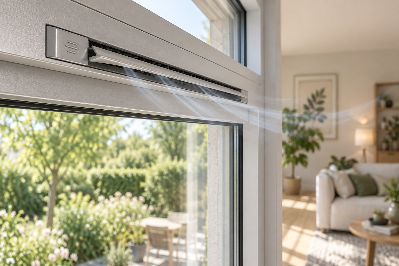
That unglamorous component deserves more attention than most project teams give it. In a country where System 1 natural ventilation dominates standard domestic construction, window replacement schemes, and smaller extensions, the trickle vent is effectively the frontline product that determines whether a dwelling meets or fails its approved document f ventilation 2021 obligations. Yet it's routinely treated as an afterthought, specified last, installed incorrectly, or, worst of all, handed over in the closed position with no explanation to the occupant.
A trickle vent, also called a background ventilator, is a small, controllable opening integrated into a window or door frame. It provides a continuous path for fresh outdoor air to enter a room without requiring the window to be opened. When you close your windows at night for security and noise reduction, the trickle vent keeps a measured stream of air flowing through the dwelling, preventing the sealed-box effect that traps moisture, CO₂, and volatile organic compounds indoors. It's the passive breathing mechanism that makes System 1 ventilation work around the clock.
Consider what System 1 actually asks the building to do. Intermittent extract fans in wet rooms handle the intense, localised bursts of moisture and odour from cooking and bathing. But those fans can only remove air. For every litre per second they extract, an equivalent volume of replacement air must enter the dwelling from somewhere. In a reasonably airtight modern home, that replacement air isn't seeping through gaps around poorly fitted windows the way it did in older properties. It enters through the trickle vents.
Without sufficient background ventilation, intermittent extract fans starve. They spin at full speed but move progressively less air as the internal pressure drops with nowhere for make-up air to come from. The result is reduced effective extract rates, rising humidity, and condensation forming on cold surfaces: precisely the conditions the approved document f ventilation gov.uk guidance exists to prevent.
The minimum equivalent area requirements published in the gov.uk approved document f ventilation 2021 pdf make the stakes clear. As industry guidance from WindowWare confirms, multi-storey dwellings require a minimum of 8,000 mm² equivalent area (EQA) per habitable room and kitchen, while single-storey dwellings such as bungalows and ground-floor flats need 10,000 mm² EQA for those same rooms. Bathrooms across all property types require a minimum of 4,000 mm² EQA. These aren't suggestions. Fall short of these figures, and the installation won't satisfy building regulations.
For replacement windows, the position is equally firm. If the original windows had trickle vents, the new ones must provide at least the same equivalent area, never less. If the original windows had no background ventilators at all, the new installation must now include them to bring the property up to current Part F standards. A common misconception is that a night-latch position, locking the window slightly ajar, qualifies as background ventilation. It does not. Night vents fail to deliver the secure, consistent, controllable airflow that the regulations demand.
Selecting the right trickle vent involves more than grabbing the cheapest option from a catalogue. Three specification criteria determine whether a vent will actually deliver compliant performance in the field, and getting any one of them wrong can mean a failed inspection or an occupant complaint that circles back to the installer.
Equivalent area (EQA). This is the measure of a vent's airflow performance, expressed in mm². It represents the effective free area through which air can pass, accounting for the resistance created by the vent's internal baffles, grilles, and control mechanism. Physical size alone is misleading because two vents of identical external dimensions can have very different equivalent areas depending on their internal geometry. Always check the manufacturer's tested EQA figure rather than assuming a larger vent automatically delivers more airflow.
If one vent doesn't reach the required threshold for a room, multiple units can be combined. For example, achieving 8,000 mm² EQA for a living room window in a two-storey house could involve two vents rated at 4,000 mm² each, or a combination of a 5,000 mm² vent and a 3,000 mm² vent. The principle is simple: it's always better to over-specify than to fall short.
Acoustic performance. In noise-sensitive locations, whether near busy roads, rail lines, flight paths, or dense urban centres, standard trickle vents can become a weak point in the building's sound insulation. Acoustic trickle vents use internal baffles and sound-absorbing materials to attenuate external noise while maintaining the required airflow. Specifying acoustic variants in bedrooms and living areas where occupant comfort depends on low background noise isn't just good practice. In many planning conditions, it's mandatory. Where a local authority has imposed noise mitigation requirements through planning consent, the acoustic performance of the background ventilator becomes a compliance issue beyond Part F alone.
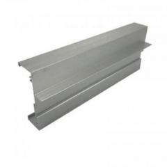
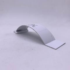
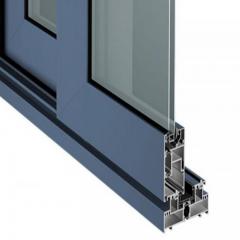
Frame compatibility. A vent must integrate physically with the window frame it's being installed into. uPVC, aluminium, and timber frames each have different profile depths, routing requirements, and fixing methods. A vent designed for a deep uPVC mullion won't sit correctly in a slimline aluminium profile, and forcing an incompatible fit risks restricted airflow, water ingress, or a vent that rattles in the wind. Manufacturers like Shengxin Aluminium address this by engineering trickle vents specifically for uPVC and aluminium window integration, with tested airflow performance and noise-conscious design that aligns with Part F requirements. Products designed for a specific frame type ensure accurate routing, secure fixing, and predictable EQA delivery without the guesswork of adapting a generic component.
With dozens of products on the market, narrowing the field to the right vent for a specific installation comes down to a structured selection process. Rushing this decision, or delegating it to whoever happens to be ordering hardware that week, is how projects end up with vents that underperform or create problems post-handover.
Fabrication accuracy deserves particular emphasis. Most trickle vents consist of two main parts: an external canopy or recessed grille that shields against weather, and an internal ventilator that gives the occupant control over airflow. The slot routed into the frame must match the manufacturer's specification precisely. A slot that's too narrow restricts airflow below the vent's rated EQA. One that's too wide compromises the seal and can allow water penetration during wind-driven rain. Detailed routing drawings, typically available on the manufacturer's product page, should be without deviation.
One final point that sounds trivial but has an outsized impact on real-world performance: every trickle vent must be handed over in the open position. The approved document f ventilation gov uk guidance is explicit on this requirement for System 1 installations. Occupants who receive their new windows with closed vents overwhelmingly leave them closed, often permanently, because they assume the default position is intentional. That single oversight, closing a vent at handover, can undo thousands of pounds' worth of compliant specification work. A brief explanation to the homeowner about what the vent does and why it should remain open costs nothing and protects both the occupant's health and the installer's reputation.
Specifying the right background ventilator is a critical step, but it's only one element in a broader compliance sequence. Pulling every thread together, from project classification through system selection to commissioning and product specification, requires a structured approach that leaves nothing to chance.
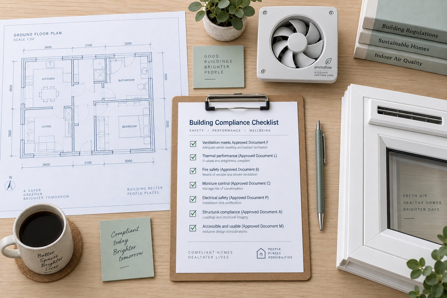
Every section of this article has addressed a different piece of the ventilation compliance puzzle. Individually, those pieces make sense. The real challenge is assembling them into a single, repeatable workflow that you can apply project after project, whether you're an architect drafting a new-build specification, a contractor replacing windows in an existing property, or a specifier coordinating between trades. Here's that workflow distilled into a clear sequence.
Think of Part F compliance as a chain. Each link depends on the one before it, and skipping a step weakens the entire strategy. The following roadmap reflects the logical order in which decisions should be made, from the earliest design stage through to handover documentation.
Step four deserves extra emphasis because product selection is where compliance either becomes tangible or falls apart. A ventilation strategy that looks perfect on a specification sheet delivers nothing if the installed products can't achieve the required equivalent areas, extract rates, or acoustic attenuation in practice. This is especially true for background ventilators in System 1 installations, where the trickle vent is the only component standing between a compliant dwelling and a sealed box that traps moisture and pollutants.
When evaluating products, demand tested performance data rather than relying on physical dimensions alone. Confirm that the manufacturer provides equivalent area figures derived from standardised testing, not estimated from slot size. Check that acoustic variants are available for noise-sensitive locations. Verify frame compatibility before ordering, because retrofitting an incompatible vent on site wastes time and compromises airflow performance. Resources like the Shengxin Aluminium trickle vent product page provide the kind of technical specification detail, including airflow data and frame integration guidance, that makes informed product selection straightforward.
Part F compliance is a design decision, not an afterthought. The projects that sail through building control are the ones where ventilation was planned from the first sketch, not patched in after the windows were already on order.
This approved document f summary comes down to a simple principle: treat ventilation with the same rigour you'd apply to structural calculations or fire strategy. Identify what the building needs, select the right system and products, verify that everything performs as designed, and document the results. Every step in this roadmap exists because skipping it has, on real projects, led to failed inspections, costly rework, or homes that made their occupants unwell. Follow the sequence, and the approved document f ventilation 2021 pdf gov uk requirements become a checklist you can work through with confidence rather than a regulatory maze that trips you up on site.
Approved Document F is statutory guidance published by the UK government showing how to satisfy Part F (ventilation) of the Building Regulations 2010 in England. It is not the law itself. The legal obligation comes from Requirement F1 in Schedule 1, which states that adequate means of ventilation must be provided for building occupants. Approved Document F offers one accepted method of compliance, but designers may use alternative approaches provided they can demonstrate the functional requirement is met. Following the approved document creates a presumption of compliance, while deviating from it shifts the burden of proof to the designer.
Yes. Under the current Approved Document F Volume 1, replacement windows in existing dwellings must include background ventilators that meet minimum equivalent area (EQA) requirements. If the original windows had trickle vents, replacements must provide at least the same EQA. If the originals had none, the new windows must still incorporate compliant background ventilators to meet current Part F standards. A night-latch position does not qualify as background ventilation, and homeowners cannot opt out via a disclaimer. Products such as Shengxin Aluminium's Window Trickle Vents are engineered for uPVC and aluminium frame integration with tested EQA ratings to simplify compliance.
Approved Document F recognises four ventilation systems for dwellings. System 1 uses natural ventilation via trickle vents combined with intermittent extract fans in wet rooms, and it is the most common choice for standard houses and window replacements. System 2 is continuous mechanical extract ventilation (cMEV), where a central fan runs constantly at a low rate with boost capability. System 3 is continuous mechanical supply ventilation (cMSV), drawing filtered air into habitable rooms via ductwork. System 4 is mechanical ventilation with heat recovery (MVHR), which simultaneously supplies and extracts air through a heat exchanger recovering up to 93% of outgoing warmth, making it ideal for airtight, high-performance homes.
For intermittent extract under System 1, a kitchen with a cooker hood adjacent to the hob requires a minimum of 30 litres per second (l/s), while a kitchen fan positioned away from the hob must deliver 60 l/s. Bathrooms with a bath or shower need 15 l/s, and a WC or cloakroom requires 6 l/s. Bathroom and WC fans must include a 15-minute run-on timer to clear residual moisture after use. Continuous systems have separate low-rate and boost-rate figures. The whole-dwelling background ventilation rate scales by bedroom count, starting at 19 l/s for a one-bedroom dwelling and rising to 43 l/s for five or more bedrooms.
Part L (Conservation of Fuel and Power) drives tighter building envelopes, which eliminates the accidental air leakage older buildings relied on for ventilation. This makes planned, controlled ventilation under Part F essential rather than optional. Over-ventilating wastes energy under Part L, while under-ventilating breaches Part F. Part O (Overheating), introduced alongside the 2022 edition of Approved Document F, requires new residential buildings to demonstrate they will not overheat. Purge ventilation openings and window free areas must satisfy both Part F rapid air change requirements and Part O overheating thresholds simultaneously, meaning these elements should be designed as a coordinated package.



 Интернет Сервис
 0086 136 3563 2360
 sales@sxalu.com
 +86 136 3563 2360
 русский
 English
 français
 Deutsch
 español
 português
 العربية
 ไทย
ไทย Việt
Việt Українська