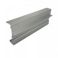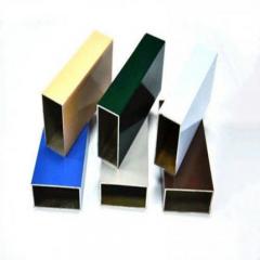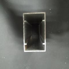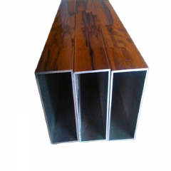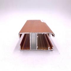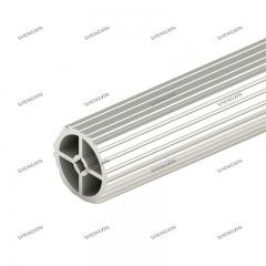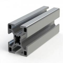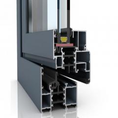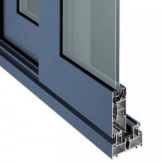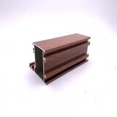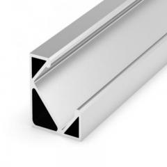
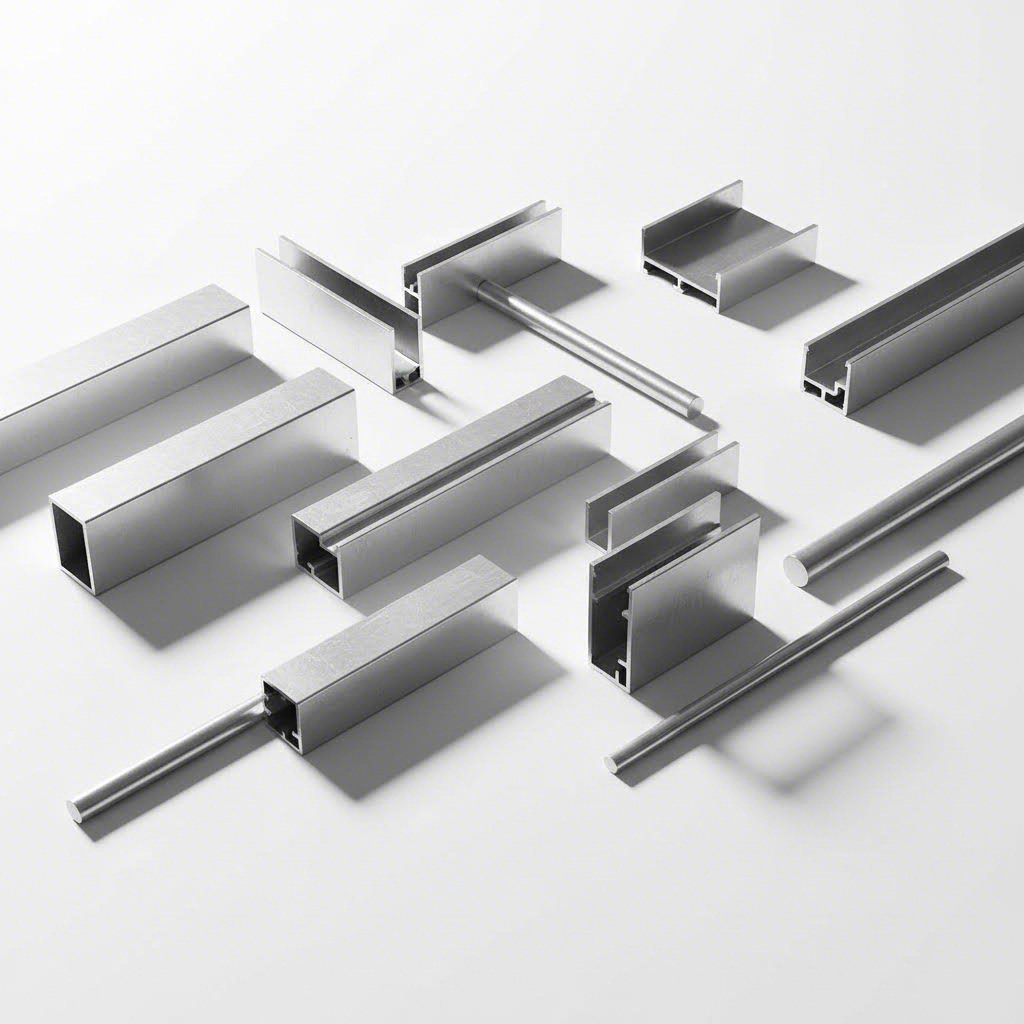
Ever wondered how engineers determine exactly how much aluminum they need for a project? An aluminum weight calculator is a tool that helps you determine the weight of aluminum based on its dimensions and material properties. Whether you're planning a construction framework, designing custom machinery, or ordering materials for manufacturing, understanding the weight of aluminum extrusions is essential for accurate project planning.
At its core, every material calculator for aluminum relies on a simple relationship: the cross-sectional area of your profile, multiplied by its length, and then multiplied by the density of the specific aluminum alloy. This equation of weight forms the foundation of all accurate estimates, from quick napkin calculations to sophisticated CAD software outputs.
The fundamental equation driving every aluminum extrusion weight calculation is surprisingly straightforward:
Weight = Cross-Sectional Area × Length × Density
Let's break this down into practical terms. The cross-sectional area (CSA) is simply the area of a "slice" of your aluminum profile. For a basic square bar measuring 30mm × 30mm, the calculation is just 30 × 30 = 900mm². For more complex shapes, you may need to break the profile into simpler geometric components or use CAD software to determine the precise area.
The length is measured in your preferred unit (meters or feet), while density depends on your specific aluminum alloy. Most common extrusion alloys like 6063 have a density of approximately 0.0027 kg/cm³ or 2,700 kg/m³. Together, these three variables give you the theoretical weight of any aluminum extrusion.
A quick note on terminology: while we commonly say "weight," engineers often distinguish between mass and weight. The mass of aluminum refers to the amount of matter present, measured in kilograms or pounds. Weight technically refers to the gravitational force acting on that mass. For practical purposes in ordering and shipping, we use these terms interchangeably, but understanding the aluminum mass calculation ensures precision in engineering contexts.
Why should you care about getting these numbers right? Accurate weight calculations directly impact three critical areas of your project:
Consider a real-world example: a 6063 aluminum square bar with a 900mm² cross-section has a theoretical weight of 2.43 kg per meter. Order a 6.3-meter length, and you're looking at approximately 15.31 kg per piece. Scale that across hundreds of pieces, and even small calculation errors compound quickly.
With aluminum's density of around 2,700 kg/m³, it weighs roughly one-third as much as steel, making it a popular choice when weight savings matter. However, this advantage only translates to real cost savings when you calculate precisely from the start.
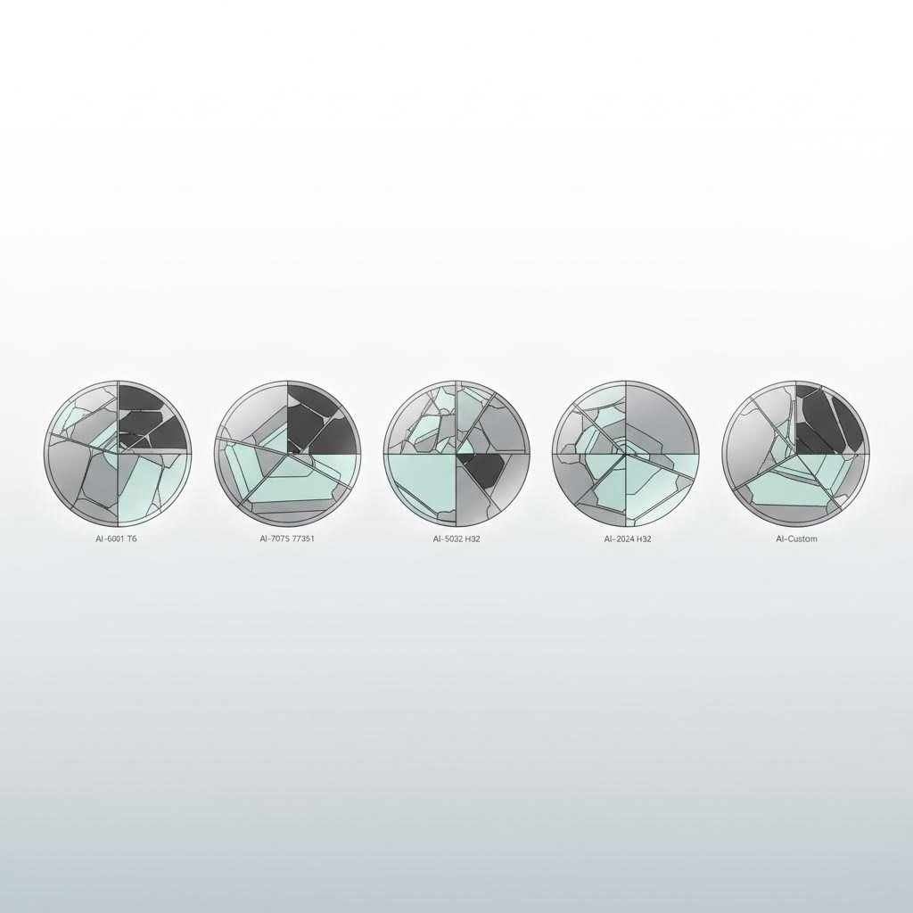
Now that you understand the core formula, the next critical piece of the puzzle is knowing the exact density of your chosen alloy. Here's where many weight calculations go wrong: using a generic "aluminum density" value when the actual density of aluminium varies significantly between alloy families. The difference between a 5052 alloy and a 7075 alloy can shift your weight estimate by over 4%, enough to throw off shipping quotes and material budgets on large orders.
What is aluminium density exactly? Pure aluminum has a density of approximately 2.70 g/cm³, but the moment you add alloying elements like magnesium, silicon, copper, or zinc, that number changes. Some elements decrease density while others increase it. Understanding these variations is essential for accurate weight calculations in any extrusion project.
The table below provides verified density values for the most commonly used aluminum extrusion alloys. When using an aluminum weight calculator, selecting the correct alloy-specific density ensures your results match real-world measurements.
| Alloy Designation | Density (lb/in³) | Density (kg/m³) | Common Applications |
|---|---|---|---|
| 6063 | 0.0975 | 2700 | Architectural extrusions, window frames, door frames, decorative trim |
| 6061 | 0.0975 | 2700 | Structural components, automotive chassis, marine fittings, bicycle frames |
| 5052 | 0.0968 | 2680 | Marine applications, fuel tanks, pressure vessels, appliances |
| 2024 | 0.1004 | 2780 | Aerospace structures, aircraft fuselage, wing skins, high-stress components |
| 7075 | 0.1015 | 2810 | Aerospace, military equipment, high-performance automotive, sports gear |
Source: Worthwill Aluminum Density Table, referencing Aluminum Association (AA) standards and verified materials databases.
Notice the density of aluminum lb/in3 values range from 0.0968 for 5052 to 0.1015 for 7075. That's roughly a 5% difference. When you're ordering 1,000 feet of extrusion, this variance translates directly into pounds of material and dollars on your invoice.
For those working in metric units, the density aluminium 6061 value of 2700 kg/m³ is identical to 6063, making these two alloys interchangeable for weight estimation purposes. However, as we'll explore below, the density of aluminum in lb in3 for aerospace-grade alloys like 2024 and 7075 is noticeably higher due to their copper and zinc content.
Why is 6063 the most popular aluminum extrusion alloy worldwide? Beyond its excellent surface finish and corrosion resistance, 6063 offers optimal extrudability. Its magnesium and silicon composition flows smoothly through extrusion dies, enabling complex profiles with thin walls and intricate geometries. The aluminum alloy 6061 density matches 6063 exactly at 2700 kg/m³, but 6061 provides higher strength, making it the go-to choice for structural applications where load-bearing capacity matters more than decorative finish.
The density aluminum 6061 T6 temper, the most common heat-treated condition, remains at 0.0975 lb/in³. Heat treatment affects mechanical properties like tensile strength and hardness but does not significantly change the alloy's density. This means your weight calculations remain valid regardless of temper designation.
Here's a practical example of how alloy selection impacts weight:
That 2.4-pound difference per 100 feet might seem small, but scale up to a production run of 10,000 feet and you're looking at 240 extra pounds of material. For aerospace applications requiring 7075's superior strength, this weight penalty is acceptable. For architectural applications where 6063 meets all requirements, choosing the lighter alloy saves both material cost and shipping expense.
The 5000-series alloys like 5052 offer the lowest densities among common extrusion materials because magnesium is lighter than aluminum itself. When corrosion resistance in marine environments is your priority, 5052 delivers excellent performance with a slight weight advantage over the 6000-series alloys.
Understanding these density variations between alloy families empowers you to make informed decisions. With your alloy-specific density value in hand, the next step is applying it to actual profile geometries, starting with the most common standard shapes.
Ready to put theory into practice? Whether you're using a bar weight calculator for solid extrusions or a tube weight calculator for hollow profiles, the fundamental process remains the same. The difference lies in how you calculate the cross-sectional area for each shape. Let's walk through the exact steps for the most common aluminum extrusion profiles you'll encounter.
Every bar weight calculation follows a simple four-step process that applies regardless of profile complexity:
Sounds straightforward? It is, once you know the right formulas for each shape. Let's break down solid and hollow profiles separately.
Solid profiles are the simplest to calculate because you're working with basic geometric shapes without any voids to subtract. The most common solid extrusions include rectangular bars, round rods, and square bars.
Rectangular Bar Example:
Imagine you need to calculate the weight of a 6061 aluminum flat bar measuring 50mm wide × 10mm thick × 2 meters long.
Round Rod Example:
A rod weight calculator uses the circle area formula. For a 6063 aluminum rod with a 25mm diameter and 1.5-meter length:
For quick reference, here's a summary of cross-sectional area formulas for solid profiles:
| Profile Type | Cross-Sectional Area Formula | Variables |
|---|---|---|
| Rectangular Bar | A = width × height | w, h in same units |
| Square Bar | A = side² | s = side length |
| Round Rod | A = π × radius² | r = diameter ÷ 2 |
| Hexagonal Bar | A = (3√3 ÷ 2) × side² | s = flat-to-flat ÷ 1.155 |
Hollow profiles require an extra step: calculating the outer area and subtracting the inner void. This is where the weight of pipe calculation differs from solid bar calculations. The principle is simple: material area = outer area minus inner area.
Round Tube Example:
Consider a 7075 aluminum round tube with a 50mm outer diameter, 3mm wall thickness, and 1.5-meter length. This is exactly how a weight of a pipe calculator handles the geometry:
There's actually a simplified formula for round tubes that eliminates the need to calculate inner and outer areas separately:
Tube Weight = (OD - t) × t × π × L × density
Where OD = outer diameter, t = wall thickness, and L = length. This formula works because (OD - t) represents the mean diameter, and multiplying by wall thickness and π gives you the cross-sectional area directly.
Square Tube Example:
For a square tube measuring 40mm × 40mm with 2mm wall thickness and 3-meter length in 6063 aluminum:
An alternative engineering formula for square tubes is: W = 4t(A + B - 2t) × L × ρ, where A and B are the outer dimensions. According to verified engineering calculations, this accounts for the perimeter multiplied by wall thickness minus the corner overlaps.
Pro Tip for Measuring Wall Thickness:
Accurate wall thickness measurement is critical for hollow profile calculations. Here's how to get reliable readings:
Angle Profile Example:
Angle profiles (L-shapes) are calculated by treating them as two connected rectangles. For a 50mm × 50mm × 5mm equal angle in 6061 aluminum, 2 meters long:
While these examples focus on aluminum, the same geometric principles apply if you're using a steel pipe weight calculator. The only difference is substituting steel's density (approximately 7.85 g/cm³) for aluminum's much lighter 2.7 g/cm³. This density difference explains why aluminum extrusions weigh roughly one-third as much as equivalent steel profiles.
With standard profiles mastered, what happens when your project requires something more complex than simple rectangles and tubes? Custom extrusion profiles with multiple cavities, varying wall thicknesses, and irregular geometries demand a different approach.
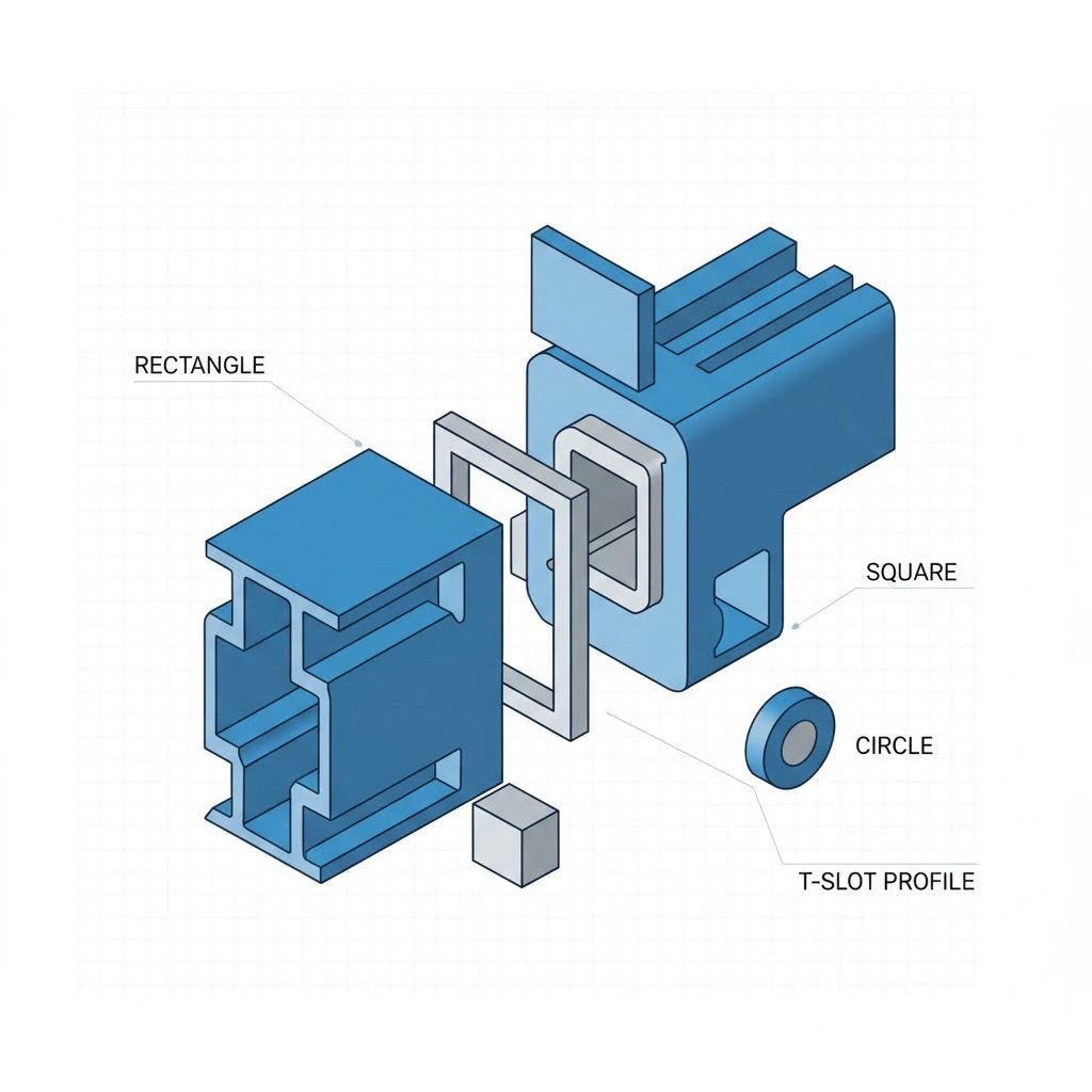
What happens when your extrusion profile doesn't fit neatly into a standard rectangle, tube, or angle category? Custom profiles with T-slots, multiple cavities, or asymmetrical geometries present a real challenge when calculating metal weight. The good news? You don't necessarily need expensive CAD software to get accurate results. The decomposition method allows you to break complex shapes into manageable pieces using nothing more than basic geometry and a calculator.
Think of it like solving a puzzle in reverse. Instead of assembling pieces into a complete picture, you're identifying the simple geometric components that make up your complex profile. Once you calculate the area of each component, you simply add the solids and subtract the voids to arrive at your total cross-sectional area.
Every complex aluminum extrusion, no matter how intricate, is composed of basic geometric elements. The key to manual weight calculation lies in recognizing these building blocks. Here are the most common components you'll encounter in custom extrusion profiles:
According to industry guidance from extrusion specialists, if your profile is made up of lots of smaller squares, rectangles, and triangles, you can work out the area of each and then add them up to get the total cross-sectional area.
Practical Example: T-Slot Profile
Imagine you're working with a custom T-slot extrusion measuring 40mm × 40mm overall. Rather than struggling with the complex geometry, decompose it:
When tackling multi-cavity extrusions, the key principle is straightforward: calculate the bounding solid shape first, then subtract each cavity individually. This approach works for everything from simple two-cavity tubes to complex heatsink profiles with dozens of fins.
Step-by-Step Process for Multi-Cavity Profiles:
For profiles with irregular outer boundaries (not fitting a simple rectangle), you'll need to add positive areas rather than subtract negatives. Calculate each solid section separately and sum them together.
Handling Varying Wall Thicknesses
Many custom extrusions feature non-uniform walls for structural or thermal reasons. When calculating weight for these profiles:
To put this in perspective, the weight of aluminum per cubic inch is approximately 0.0975 lb for common 6063 alloy. This means every cubic inch of material in your complex profile contributes nearly a tenth of a pound. When you're dealing with the aluminium weight per cubic inch in metric terms, that's roughly 2.7 grams per cubic centimeter.
When Manual Methods Reach Their Limits
The decomposition method works well for profiles where you can clearly identify geometric components. However, as profiles become more organic in shape or feature curved surfaces and complex internal geometries, manual calculations become increasingly error-prone. According to extrusion design experts, for highly complicated shapes, you will probably need to use CAD software to calculate the area accurately.
For those working on aluminium material weight calculator needs without CAD access, here are practical alternatives:
The weight of aluminium per cubic inch remains constant for any given alloy, regardless of how complex your profile becomes. Whether you're working with a simple bar or an intricate heatsink, mastering the decomposition method gives you the tools to estimate weights confidently before investing in CAD software or professional engineering services.
Now that you can tackle custom profiles, how do these calculations compare to real-world standard weights? Industry reference tables provide valuable benchmarks for validating your calculations.
Sometimes you need a quick answer without running through calculations. Whether you're estimating material costs for a bid, verifying your manual calculations, or simply planning freight logistics, having reliable weight-per-foot reference data at your fingertips saves valuable time. These standard extrusion weight tables serve as benchmarks that help you catch calculation errors before they become costly ordering mistakes.
Think of these reference values as your sanity check. When your calculated weight for a custom profile falls wildly outside the range of similar standard shapes, that's your signal to double-check your math. Professional estimators regularly cross-reference their calculations against known standards, and you should too.
The tables below provide verified weight data for the most commonly ordered aluminum extrusion profiles in 6061-T6 alloy. These values come directly from manufacturer specifications and represent estimated weights per linear foot.
Aluminum Angle Profiles (6061-T6)
Equal and unequal leg angles are among the most versatile extrusion shapes. Here's how weight scales with size and thickness:
| Size (A × B) | Thickness (inches) | Weight (lb/ft) | Weight (kg/m) |
|---|---|---|---|
| 1" × 1" | 0.125 | 0.282 | 0.42 |
| 1" × 1" | 0.250 | 0.524 | 0.78 |
| 1.5" × 1.5" | 0.125 | 0.431 | 0.64 |
| 1.5" × 1.5" | 0.250 | 0.826 | 1.23 |
| 2" × 2" | 0.188 | 0.868 | 1.29 |
| 2" × 2" | 0.250 | 1.133 | 1.69 |
| 2" × 2" | 0.375 | 1.639 | 2.44 |
| 3" × 3" | 0.250 | 1.717 | 2.56 |
| 3" × 3" | 0.375 | 2.525 | 3.76 |
| 3" × 3" | 0.500 | 3.293 | 4.90 |
| 4" × 4" | 0.250 | 2.329 | 3.47 |
| 4" × 4" | 0.375 | 3.434 | 5.11 |
| 4" × 4" | 0.500 | 4.504 | 6.70 |
| 6" × 6" | 0.500 | 6.892 | 10.26 |
| 6" × 6" | 0.750 | 9.700 | 14.44 |
| 8" × 8" | 0.500 | 9.328 | 13.88 |
| 8" × 8" | 0.750 | 13.480 | 20.07 |
| 8" × 8" | 1.000 | 17.670 | 26.30 |
Unequal Leg Angles (6061-T6)
When your application requires different leg dimensions, these common unequal angle sizes provide reference points:
| Size (A × B) | Thickness (inches) | Weight (lb/ft) | Weight (kg/m) |
|---|---|---|---|
| 2" × 1.5" | 0.250 | 0.976 | 1.45 |
| 2.5" × 2" | 0.250 | 1.283 | 1.91 |
| 3" × 2" | 0.250 | 1.432 | 2.13 |
| 3" × 2" | 0.375 | 2.074 | 3.09 |
| 4" × 3" | 0.375 | 2.986 | 4.44 |
| 4" × 3" | 0.500 | 3.905 | 5.81 |
| 6" × 4" | 0.375 | 4.322 | 6.43 |
| 6" × 4" | 0.500 | 5.692 | 8.47 |
| 8" × 6" | 0.750 | 11.680 | 17.39 |
How do you use these reference values effectively? Start by identifying the standard profile closest to your required dimensions. If your custom profile falls between listed sizes, interpolation gives you a reasonable estimate. For instance, a 2.5" × 2.5" × 0.250" angle should weigh somewhere between the 2" × 2" × 0.250" (1.133 lb/ft) and 3" × 3" × 0.250" (1.717 lb/ft) values listed above.
Using Reference Weights as Calculation Benchmarks
These standard weights serve several practical purposes beyond quick estimates:
Notice how weight increases non-linearly with wall thickness. Doubling the thickness of a 2" × 2" angle from 0.188" to 0.375" nearly doubles the weight (0.868 to 1.639 lb/ft). This relationship holds across all profile types and provides a useful mental check when evaluating your calculations.
For those familiar with i beam weight calculator tools or steel tube weight calculator applications, the process is identical. Only the density values differ. Aluminum angles at comparable dimensions weigh roughly one-third of their steel tube weight equivalents, which explains why aluminum dominates applications where weight reduction justifies the material premium.
When you need precise weights for structural applications, a dedicated weight calculator for i beam profiles or your specific geometry remains essential. However, these plate weight reference tables provide the foundation for confident preliminary estimates and serve as reliable checkpoints throughout your project planning process.
Of course, these theoretical weights assume perfect manufacturing conditions. In reality, extrusion tolerances create variations between calculated and delivered weights, a critical factor we'll examine next.
You've mastered the formulas, selected the right alloy density, and calculated your theoretical aluminum weight down to the gram. But here's a reality check: the extrusion that arrives at your loading dock will almost never match that calculated number exactly. The gap between theoretical and actual aluminium weight exists because manufacturing is not a perfect process. Understanding this difference prevents ordering headaches, budget surprises, and project delays.
According to industry analysis from extrusion specialists, the existence of profile thickness tolerance determines the disparity between weighing and theoretical weights. This isn't a quality defect. It's an inherent characteristic of the extrusion process that every buyer should factor into their material planning.
Every aluminum extrusion leaves the die with slight dimensional variations. These aren't flaws; they're the natural result of thermal dynamics, die wear, and material flow characteristics. The question isn't whether your aluminum weights will vary from calculations, but by how much.
Consider this real-world example: an aluminum profile with a theoretical weight of 1.038 kg/m and a wall thickness of 1.4mm carries a standard tolerance of ±0.13mm. With a positive tolerance of +0.13mm, the actual weight becomes 1.093 kg/m. With a negative tolerance of -0.13mm, it drops to 0.982 kg/m. For a 963-meter order, this translates to a weight difference of approximately 53 kg per piece.
That's a 5% swing from a single tolerance variable. When you understand the unit weight of aluminum at 2,700 kg/m³, you can see how small dimensional changes compound across large orders.
Multiple factors contribute to the gap between your calculated wt of aluminium and what the scale reads at delivery. Here are the primary sources of weight variation:
Surface Treatment Weight Additions
If your project specifies surface-treated extrusions, factor in these additional weights:
Packaging Material Weight
Don't overlook what's wrapped around your extrusions. For paper-wrapped packaging, weight is typically limited to a maximum of 6% of total profile weight. Shrink-wrap packaging generally adds around 4%. On a one-tonne order, that's 40kg to 60kg of non-aluminum material you might be paying for if settlement is based on gross weight.
Adding Safety Margins to Your Orders
Given these real-world variations, how should you adjust your material orders? Here's practical guidance:
The closer actual thickness runs to theoretical thickness, the closer your delivered aluminium weight aligns with calculated values. Quality-focused manufacturers maintain tighter control over die wear and process parameters, resulting in more predictable weights. When weight consistency matters for your application, this becomes a supplier selection criterion worth discussing upfront.
Understanding these tolerance realities helps you budget accurately and avoid unpleasant surprises. But how does aluminum's weight compare to other materials you might consider for your project? The next section puts aluminum in perspective against steel and other metals.
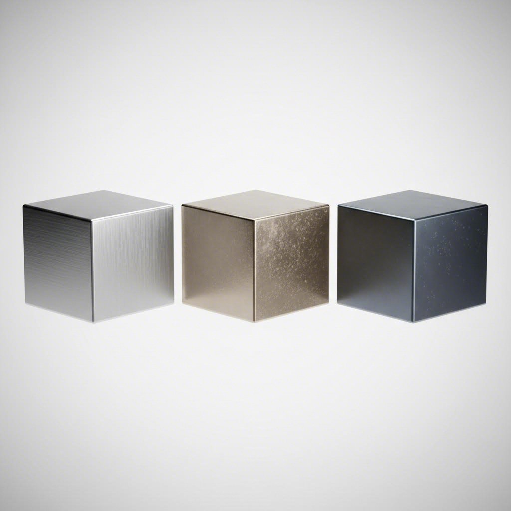
Now that you understand how manufacturing tolerances affect real-world weights, let's zoom out and ask a bigger question: how does aluminum stack up against other metals you might consider? When evaluating aluminum vs steel weight differences, the numbers tell a compelling story. Aluminum weighs roughly one-third as much as steel for equivalent volumes, a difference that translates directly into cost savings, performance gains, and design possibilities across countless applications.
But weight alone doesn't tell the whole story. How much does steel weigh compared to its load-bearing capacity? How much does aluminum weigh when you factor in the thicker sections needed to match steel's strength? The answer depends on your specific application, which is why understanding metals by weight alongside their mechanical properties helps you make smarter material decisions.
The fundamental difference between aluminum and steel comes down to density. According to material science research, carbon steel has a density approximately three times that of aluminum alloys. This means a cubic inch of steel weighs nearly three times more than the same volume of aluminum.
Here's how common structural metals compare across key weight-related properties:
| Metal | Density (lb/in³) | Density (kg/m³) | Relative Weight vs Aluminum | Typical Tensile Strength (MPa) | Strength-to-Weight Ratio |
|---|---|---|---|---|---|
| Aluminum 6061-T6 | 0.0975 | 2,700 | 1.0 (baseline) | 310 | High |
| Carbon Steel | 0.284 | 7,850 | 2.9× | 500 | Moderate |
| Stainless Steel 304 | 0.289 | 8,000 | 3.0× | 515 | Moderate |
| Titanium Grade 5 | 0.160 | 4,430 | 1.6× | 950 | Very High |
Notice something interesting? While steel offers higher absolute strength, the weight of aluminium vs steel tells a different story when you consider the strength-to-weight ratio. As engineering analysis confirms, despite steel's greater strength, aluminium's lower density provides a superior strength-to-weight ratio when the two are compared directly.
Let's put this in practical terms. Stainless steel weight for a 1-foot length of 2" × 2" × 0.25" angle comes in around 3.4 lb. The equivalent aluminum angle weighs approximately 1.13 lb. That's a 2-pound difference per linear foot. Scale that across a 500-foot project, and you're looking at 1,000 pounds of weight savings by choosing aluminum.
Titanium weight falls between aluminum and steel, offering an exceptional strength-to-weight ratio that makes it the premium choice for aerospace and high-performance applications. However, titanium's significantly higher cost limits its use to situations where performance justifies the investment.
So when does aluminum's weight advantage justify its typically higher material cost compared to steel? The answer depends on how weight impacts your specific application's performance, efficiency, and total cost of ownership.
Transportation Applications
Every pound matters when that pound needs to move. According to industry analysis, in airplane construction, weight is a critical factor for fuel efficiency and performance. Aluminum's lightness makes it a better choice for aircraft bodies, even though steel is still used for critical components like engines and landing gear. The same logic applies to trucks, trailers, railcars, and marine vessels where reduced weight translates directly to fuel savings over the vehicle's lifetime.
Portable Equipment
When humans need to carry, lift, or maneuver equipment, lighter materials reduce fatigue and improve usability. Aluminum extrusions dominate applications like portable staging, camera equipment, ladders, and scaffolding where operators handle the equipment repeatedly throughout the workday.
Aerospace Components
The aerospace industry pioneered aluminum's widespread industrial use precisely because of its weight advantages. As material science research notes, lighter and more fuel-efficient aircraft are made possible by aluminum alloys. Every kilogram saved in airframe weight allows for additional payload, extended range, or reduced fuel consumption.
Here are the industries where weight calculations drive material selection decisions:
The decision between aluminum and steel isn't always straightforward. Material selection experts recommend evaluating several factors: strength requirements, corrosion exposure, budget constraints, and weight sensitivity. For static structures where weight has minimal operational impact, steel's lower cost often wins. For anything that moves, flies, or gets carried, aluminum's weight advantage frequently delivers long-term value that exceeds its upfront premium.
With this comparative context in mind, you're now equipped to make informed material choices. But knowing which metal to use is only part of the equation. The next section explores how to apply your weight calculations to real project decisions, from shipping quotes to structural verification.
You've calculated the theoretical weight, factored in tolerances, and compared aluminum to alternative materials. Now what? The real value of accurate weight data emerges when you apply it to actual project decisions. From negotiating freight rates to verifying that your structure can handle the load, your material weight calculator results directly influence budgets, timelines, and engineering outcomes.
Think of weight calculations as the foundation for three critical project activities: estimating shipping costs, ordering the right material quantities, and confirming structural capacity. Get any of these wrong, and you're facing budget overruns, project delays, or safety concerns. Let's walk through each application with practical examples.
Freight carriers don't guess at shipping costs; they calculate them based on weight, dimensions, and distance. Your ability to provide accurate weight data directly affects the quotes you receive and whether those quotes hold up when your shipment hits the scale.
Here's the reality: underestimate your shipment weight by 10%, and you'll face reweigh fees, delayed shipments, and revised invoices that blow your logistics budget. Overestimate by the same margin, and you're paying for capacity you don't need.
Complete Example: Freight Quote Calculation
Imagine you're ordering aluminum angle extrusions for a commercial installation project. Let's walk through the entire process from profile selection to final shipping weight:
This systematic approach prevents the frustrating scenario where your freight bill arrives 15% higher than quoted because actual weights exceeded your estimate. As noted in industry pricing guidance, shipping cost is a real addition to your total purchase cost that must be calculated accurately.
For projects involving multiple profile types, create a simple weight summary table:
| Profile Description | Quantity (ft) | Weight/ft (lb) | Subtotal (lb) |
|---|---|---|---|
| 3" × 3" × 0.375" Angle | 2,400 | 2.525 | 6,060 |
| 2" × 2" × 0.250" Angle | 800 | 1.133 | 906 |
| 4" × 3" × 0.500" Angle | 400 | 3.905 | 1,562 |
| Net Aluminum Weight | 8,528 | ||
| 5% Tolerance Buffer | 426 | ||
| 4% Packaging | 358 | ||
| Estimated Gross Weight | 9,312 lbs |
When aluminum extrusions serve as structural components, engineers must account for dead load, the constant weight of the structure itself. Underestimating material weight means underestimating the forces acting on connections, foundations, and supporting members.
Consider a canopy structure where aluminum extrusions form the framework. The steel weight calculator approach applies equally to aluminum: calculate the self-weight of every member, sum them, and add that figure to your live load calculations (wind, snow, occupancy). This total determines whether your connections and foundations are adequately sized.
Structural Verification Example:
You're designing a suspended equipment rack using 2" × 2" × 0.250" aluminum angles. The rack spans 8 feet and must support 500 lbs of equipment.
The weight of metals in your structure isn't negligible, especially as spans increase. A steel weight calculator would show even higher self-weight for equivalent steel framing, which is precisely why aluminum dominates applications where dead load reduction matters.
Perhaps the most direct application of weight calculations is ordering the right amount of material. According to aluminum pricing experts, you should always add a 5-10% waste allowance when ordering aluminum extrusions, because cutting loss and scrap generate leftover material.
Here's how accurate weight data prevents ordering mistakes:
As industry guidance confirms, weight might vary from quoted to actual, so always confirm weight per foot or meter with your supplier before finalizing orders.
Working with Experienced Extrusion Suppliers
For custom profiles where standard weight tables don't apply, partnering with a capable manufacturer becomes essential. Experienced extrusion suppliers like Shengxin Aluminium, with their 35 advanced extrusion presses and comprehensive deep processing capabilities, can provide precise weight specifications for custom profiles from die development through mass production. This eliminates the guesswork from calculating weight of steel alternatives or complex aluminum geometries.
Rather than struggling with manual decomposition methods for intricate profiles, manufacturers with integrated CAD and engineering support deliver exact weight-per-foot data calculated directly from die designs. This precision flows through to accurate freight estimates, proper material ordering, and reliable structural calculations, all stemming from getting the weight right at the source.
Whether you're calculating steel weight for comparison purposes or determining the unit weight of steel versus aluminum for a material substitution analysis, the principles remain consistent. Accurate input data yields accurate results, and accurate results drive successful project outcomes.
With practical applications mastered, one question remains: how do you ensure your weight calculations stay accurate across different projects and profile types? The final section consolidates best practices and identifies when professional support makes the difference.

You've now journeyed from basic formulas through alloy-specific density values, standard profile calculations, and real-world tolerance factors. But knowing the theory and applying it consistently are two different challenges. How do you ensure your aluminium weight calculator results remain reliable across every project? The answer lies in establishing systematic measurement practices and knowing when professional support delivers better outcomes than solo calculations.
Whether you're using an al weight calculator for quick estimates or building detailed material schedules for major procurement, these best practices separate accurate projections from costly guesswork.
Accurate weight calculations start with accurate measurements. A metal weight calculator is only as good as the dimensional data you feed it. Here are the essential practices that experienced engineers follow:
For any online metals weight calculator to deliver reliable results, your input data must reflect actual conditions. The density aluminium value you select should match your specified alloy, not a generic approximation. Your dimensional inputs should come from calibrated instruments, not rough estimates. And your tolerance allowances should reflect the precision grade of your chosen supplier.
Manual calculations and online tools serve well for standard profiles with established geometries. But certain situations demand professional engineering support to ensure weight specifications match real-world outcomes.
Consider seeking specialist assistance when:
For complex custom profiles or high-precision applications, partnering with manufacturers who offer end-to-end technical support ensures accurate weight specifications from the earliest design stages. Shengxin Aluminium's technical team provides exactly this type of comprehensive support, from die development through mass production. Their 35 advanced extrusion presses and CNC machining centers deliver precise cutting, drilling, and finishing to meet exact specifications.
When surface treatments affect your weight calculations, having access to in-house anodizing and powder coating capabilities matters. According to research on anodizing processes, coating weight density varies significantly with tank temperature and current density during processing. Anodizing at 70°F and 18 ASF ensures optimal coating properties, but variations in these parameters affect final weight. Working with a supplier who controls these variables in-house eliminates uncertainty from your weight projections.
Before you close this guide and fire up your next aluminium weight calculator session, keep these essential points in mind:
Whether you're estimating costs for a small fabrication project or specifying materials for large-scale manufacturing, the principles covered in this guide apply universally. Start with verified density data, apply the right formulas for your profile geometry, account for real-world variations, and seek professional support when complexity or precision requirements exceed what manual methods can reliably deliver.
Your aluminum extrusion weight calculations don't have to be guesswork. With the right approach, every estimate becomes a reliable foundation for project success.
To calculate aluminum extrusion weight, use the formula: Weight = Cross-Sectional Area × Length × Density. First, measure your profile dimensions to determine the cross-sectional area. For hollow profiles, subtract the inner area from the outer area. Then multiply by the extrusion length and apply your alloy's specific density (typically 2,700 kg/m³ for 6063 alloy or 0.0975 lb/in³). For complex custom profiles, break the shape into simple geometric components, calculate each area separately, and sum them before applying the density factor.
Aluminum extrusion alloy densities vary by composition. The most common extrusion alloy, 6063, has a density of 2,700 kg/m³ (0.0975 lb/in³), identical to 6061. Marine-grade 5052 is slightly lighter at 2,680 kg/m³, while aerospace alloys like 2024 (2,780 kg/m³) and 7075 (2,810 kg/m³) are denser due to copper and zinc content. This 5% density variation between alloy families directly impacts weight calculations, so always verify your specific alloy's density rather than using generic aluminum values.
Aluminum extrusion weight per foot depends on profile geometry and alloy type. For common 6061-T6 angles: a 1" × 1" × 0.125" angle weighs 0.282 lb/ft, while a 4" × 4" × 0.500" angle weighs 4.504 lb/ft. T-slot profiles range from approximately 0.44 kg/m for 20×20mm profiles to 3.11 kg/m for 40×80mm profiles. Manufacturers like Shengxin Aluminium provide precise weight-per-foot specifications for both standard and custom profiles, eliminating calculation guesswork.
Calculated and actual weights differ due to manufacturing tolerances, surface treatments, and packaging. Wall thickness tolerances of ±0.10mm to ±0.15mm can create 3-5% weight variations. Powder coating adds 4-5% to profile weight, while paper packaging contributes up to 6% of total weight. Die wear during production also causes thickness to gradually increase, meaning profiles from the same run may vary. Always add 3-5% tolerance buffer to calculated weights when ordering materials or requesting freight quotes.
Aluminum weighs approximately one-third as much as steel for equivalent volumes. Carbon steel has a density of 7,850 kg/m³ compared to aluminum's 2,700 kg/m³—roughly 2.9 times heavier. For example, a 2" × 2" × 0.25" steel angle weighs about 3.4 lb/ft, while the equivalent aluminum angle weighs just 1.13 lb/ft. This weight advantage makes aluminum ideal for transportation, aerospace, and portable equipment applications where reduced weight improves fuel efficiency, handling, and operator comfort.



 Интернет Сервис
 0086 136 3563 2360
 sales@sxalu.com
 +86 136 3563 2360
 русский
 English
 français
 Deutsch
 español
 português
 العربية
 ไทย
 Việt
 Українська