
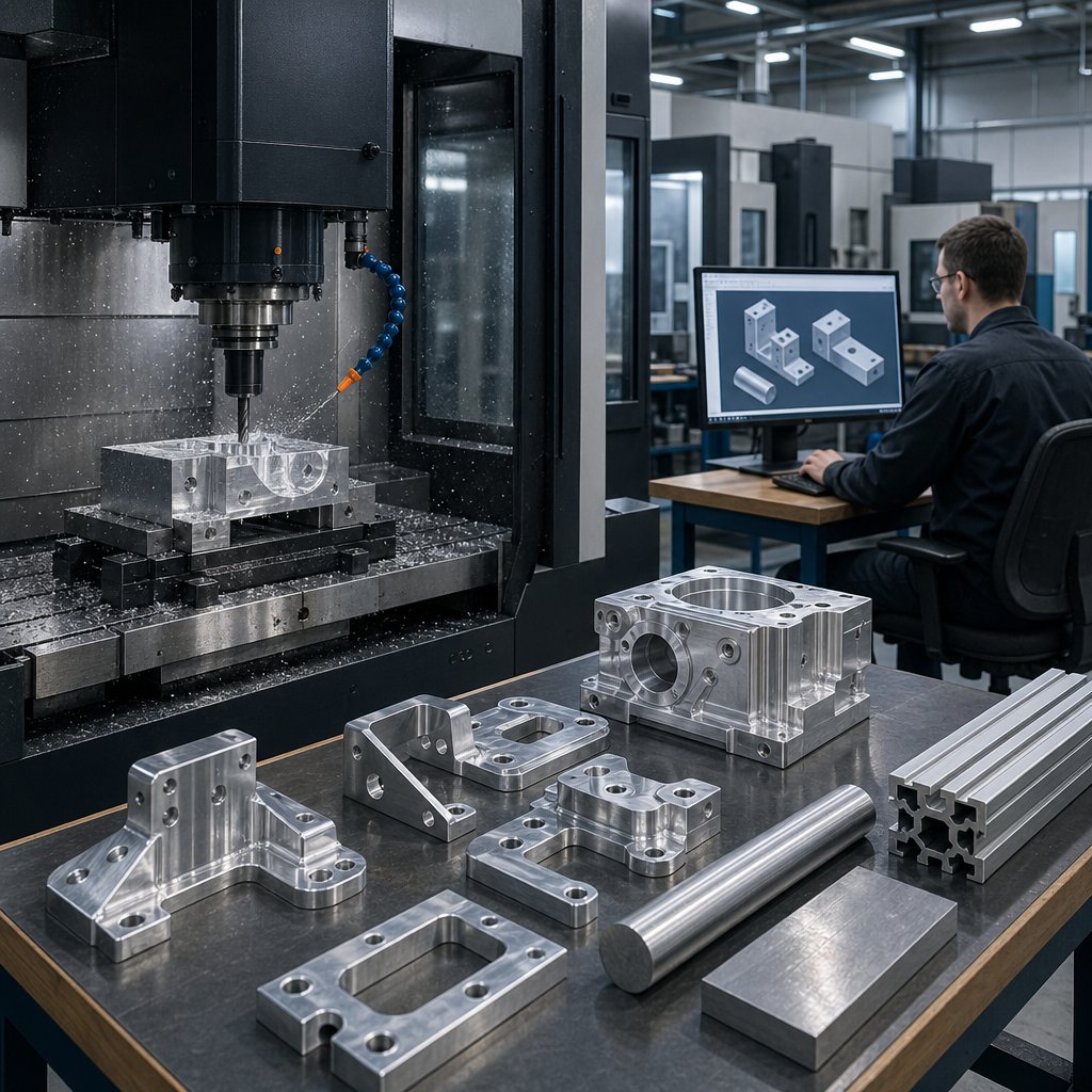
When a part needs tight dimensions, repeatable results, and a clean machined surface, aluminium cnc machining is often one of the first processes engineers consider. It shapes parts by removing material from solid aluminum stock with computer-controlled tools, making it a precise and flexible option for brackets, housings, plates, and other aluminum parts.
Aluminium CNC machining is a subtractive process that uses CNC mills, lathes, drills, and similar equipment to cut aluminum bar, billet, or plate into finished parts based on digital design data.
That simple definition matters because cnc machining aluminum is not just about making shapes. It is about making those shapes consistently, with predictable dimensions, from prototype runs to production batches. In everyday shop language, this is also part of broader aluminium machining, but with the added control and repeatability that CNC systems bring.
For planning purposes, aluminum stands out for a practical mix of properties. meviy notes that aluminum is about one-third the weight of steel, while MakerVerse highlights its natural oxide layer, which supports corrosion resistance. It also machines more easily than harder metals and accepts finishes such as anodizing, powder coating, and bead blasting.
Because of that balance, aluminum CNC machining appears across aerospace, automotive, electronics, robotics, medical devices, and industrial equipment. Common examples include heat sinks, enclosures, structural brackets, fixtures, and lightweight moving components. The catch is that not all aluminum behaves the same way, which is why alloy selection quickly becomes the real decision point.
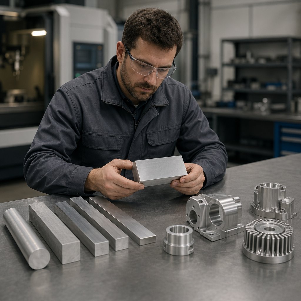
The real material choice in aluminium cnc machining is rarely a simple strength contest. It is a tradeoff between load, corrosion exposure, weldability, finish expectations, flatness, and cost. For many shops, 6061 stays the baseline because it reduces risk while machining aluminum efficiently across prototypes and production. The matrix below combines property data from Rapidaccu with application guidance from Firstmold.
For general-purpose parts, 6061-T6 is often the best aluminum for machining because it balances strength, corrosion resistance, weldability, and finishing consistency. Rapidaccu lists 6061-T6 at 310 MPa tensile strength and 275 MPa yield strength, while 7075-T6 reaches 570 MPa and 505 MPa. That gap matters, but so do the tradeoffs. This is why machining 6061 t6 aluminum is so common: it is predictable, widely available, and easier to anodize cleanly than many higher-strength grades.
7075 is the performance option when low weight and high load capacity matter most. The price is lower weldability, less forgiving corrosion behavior, and more concern about stress-corrosion cracking in harsh service. 2024 takes a different path. It offers strong fatigue performance and excellent aluminium machinability, which is why aerospace designers still specify it, but its corrosion resistance is poor and decorative anodizing is usually less attractive because of its copper content.
| Alloy | Strength snapshot | Machinability | Corrosion resistance | Weldability | Anodizing fit | Flatness or stability | Typical use pattern |
|---|---|---|---|---|---|---|---|
| 6061-T6 | 310 MPa tensile, 275 MPa yield | Good | Excellent | Excellent | Very good for consistent cosmetic color | Good in standard plate and bar | General CNC parts, brackets, housings, frames |
| 7075-T6 or T7351 | 570 MPa tensile, 505 MPa yield | Fair | Fair, watch SCC risk | Poor | Better for functional hard-coat than show surfaces | Good, but residual stress can matter in thin parts | High-load aerospace, shafts, performance hardware |
| 2024-T3 | 480 MPa tensile, 345 MPa yield | Superior | Poor | Poor | Weak cosmetic choice, copper can darken finish | Good for fatigue-critical parts, not corrosion-heavy duty | Aircraft structures, stressed lightweight components |
| 5052-H32 | 230 MPa tensile, 190 MPa yield | Moderate, can feel gummy | Superior | Excellent | Strong cosmetic potential | Better for formed or sheet-like parts than rigid blocks | Marine panels, tanks, enclosures, bent brackets |
| 6082 | Higher structural strength than 6061 in many uses | Good | Good | Good | Good for standard anodized finishes | Good for structural profiles and frames | Transport, beams, heavy-duty frames, machinery |
| MIC-6 | Not a high-strength choice | Very good | Application dependent | Not usually chosen for welded parts | Chosen more for stability than cosmetics | Excellent dimensional stability and flatness | Tooling plates, jigs, fixtures, molds, vacuum tables |
Some projects fail because the alloy was chosen like a solid block part when the design really behaves like sheet, plate, or tooling. If the job involves salt exposure, formed geometry, or welded enclosures, 5052 is often the smarter aluminum for machining overall, even though it is not the easiest cutter-friendly grade. If the part is structural and corrosion resistant but does not need aerospace-level strength, 6082 can be a strong alternative. MIC-6 belongs in its own category. When flatness, stress relief, and dimensional stability matter more than peak strength, cast tooling plate is often the cleaner answer.
If you are already comfortable with machining 6061 t6 aluminum, move away from it only when a clear part requirement justifies the change. The right aluminum for machining starts as a material decision, but it quickly becomes a process decision too, because milling, turning, drilling, and tapping do not challenge each alloy in the same way.
The alloy choice sets the baseline, but part quality is usually decided by the operation. A 6061 bracket that machines beautifully on one setup can still leave burrs, smeared walls, or rough threads on another. That is why cnc milling aluminum, drilling, reaming, and tapping need to be treated as different cutting events, not one generic process. Compared with steel, aluminum cuts with lower force but sticks to tools more easily. Compared with brass, it is less free-cutting and more prone to burrs. Compared with plastics, it handles heat better, yet soft edges can still deform when chips are recut.
In aluminium cnc milling, the goal is a true shearing cut instead of rubbing or smearing. Aluminum is soft and ductile, so a dull edge can push material ahead of the tool rather than slice it cleanly. That is when built-up edge starts forming and the finish turns cloudy or torn. Guidance from Aluphant favors sharp carbide tools, polished flutes, and climb milling because they help reduce chip adhesion and produce cleaner exits.
Workholding matters just as much. Thin walls, open pockets, and broad plates can vibrate even when cutting forces seem low. When milling aluminum, shorter tool overhang, stable clamping, and a toolpath that clears chips instead of recutting them usually do more for finish than simply pushing speed. This is why aluminum milling often looks easy until chips start welding back into the cut.
Turning aluminum usually rewards sharp, positive-geometry tools and a rigid setup. The metal does not resist the tool like steel, but it can deflect if the part is thin or poorly supported. For many aluminum cnc turning parts, the first warning signs are torn shoulders, stringy chips, or a bright finish that suddenly goes dull as the edge loads up.
Drilling brings a different problem. Aluminum tends to make long, continuous chips, so hole quality depends heavily on evacuation. Notes from Kesu highlight chip adhesion, burr formation, and the value of coolant for keeping holes cleaner. Reaming is even less forgiving. A reamer should refine an already straight, well-prepared hole. It will not correct poor alignment, wandering, or packed chips, and it can easily worsen surface finish if lubrication or stock allowance is inconsistent.
| Operation | Typical aluminum risk | Tool behavior to favor | Quality priority |
|---|---|---|---|
| Milling | Smearing, chip recutting, built-up edge | Sharp edges, polished flutes, stable engagement | Clean walls, flat floors, low burrs |
| Turning | Torn finish, stringy chips, part deflection | Positive cutting action, low runout, rigid support | Roundness, shoulder quality, consistent finish |
| Drilling and reaming | Chip packing, exit burrs, hole drift | Reliable chip evacuation, lubrication, straight entry | Hole size, straightness, smooth bore finish |
| Tapping | Chip packing, burrs, broken taps, rough threads | Tap geometry matched to hole type and alloy | Thread form, edge condition, repeatability |
Tapping is where aluminum's "gummy" behavior becomes especially obvious. Poor chip flow can scar the thread, raise burrs at the hole mouth, or break the tap outright. Shop guidance from Cutting Tool Engineering points to spiral-fluted taps for blind holes because they help pull chips back out, while form taps can eliminate chips altogether when the alloy and thread design support forming instead of cutting. Good lubrication is not optional here. It lowers friction, reduces chip welding, and helps control built-up edge.
The same material can seem effortless in one cycle and troublesome in the next. Burrs, built-up edge, finish variation, and hot chips rarely appear at random, which makes aluminum behavior worth reading like a set of symptoms rather than a simple material label.
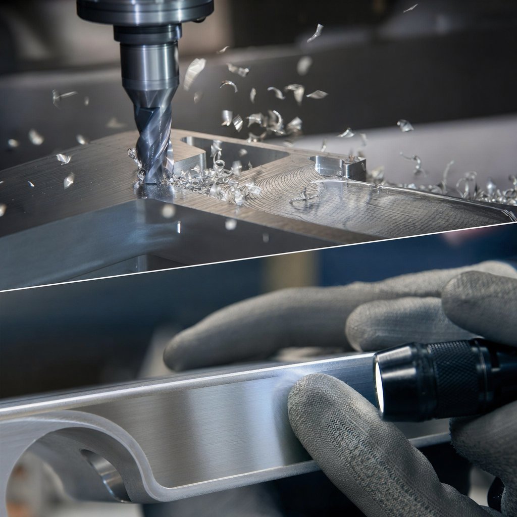
Symptoms are where aluminium cnc machining stops feeling simple. In aluminum cnc cutting, the material usually removes fast, but it also deforms, sticks, and recuts more easily than many buyers expect. That is why the cleanest diagnosis starts with what you can see first: burrs on exits, a cloudy finish, packed chips, or a tool that suddenly starts loading up.
Shop guidance from Aluphant ties burr formation to aluminum's ductile behavior. Instead of breaking away cleanly, the metal can stretch, roll over, or tear at the edge, especially when tools are dull, tool entry or exit is abrupt, clamping is weak, or coolant does not reach the cut. Built-up edge follows a similar pattern. Aluminum adheres to a hot cutting edge, then breaks away unevenly, leaving smears, roughness, and unstable size. A loaded aluminum milling cutter often shows up in the finish before it shows up on the inspection report.
Aluminum is usually easy to machine, but clean parts still depend on chip control, heat control, and a sharp cutting edge.
| Issue | Why it happens in aluminum | What to check first |
|---|---|---|
| Heavy exit burrs | Ductile metal stretches and rolls as the tool leaves the part | Tool sharpness, exit path, and support near the edge |
| Built-up edge and smearing | Soft material adheres to a hot tool and tears away unevenly | Lubrication, chip adhesion on flutes, and edge condition |
| Cloudy or torn finish | Recut chips and vibration mark the surface | Chip evacuation, tool overhang, and clamping rigidity |
| Size drift on thin features | Heat and low stiffness let the part move during cutting | Clamping pressure, roughing sequence, and finishing strategy |
| Fast tool loading or wear | Chips pack into flutes and turn cutting into rubbing | Coolant aim, flute count, and the condition of aluminum milling tools |
Surface finish problems in cnc aluminum cutting are not just cosmetic. Recut chips, chatter, and thermal movement can shift size on thin walls and broad plates. Guidance from CNCRUSH emphasizes chip evacuation, stable fixturing, and short tool overhangs, while Aluphant recommends light finishing passes and consistent tool engagement to avoid tool marks. Their finish notes also suggest Ra 1.6 to 3.2 micrometers is often acceptable for standard industrial parts, while visible or sealing faces may need under 0.8 micrometers. Many teams fixate on aluminium cutting speed milling charts first, but the better first check is whether the tool is cutting fresh material or rubbing hot chips back into the wall.
Coolant in aluminum work has two jobs at once: limit heat and carry chips away from the edge. The same sources point to water-soluble coolant, MQL, or flood cooling depending on the setup, with 2- to 3-flute carbide aluminum milling tools often preferred because they help chips clear more easily. The same warning signs also matter when cutting aluminum with a cnc router. If the machine is less rigid, chip packing and vibration show up even faster. For practical aluminum cnc cutting, start by checking:
Recurring defects rarely come from bad luck alone. Very often, the part is asking the process to machine a wall that is too thin, a hole that is too deep, or a corner that no tool can reach cleanly.
Many burr, finish, and distortion issues start in CAD long before a tool touches the stock. For aluminum cnc machining parts, design for manufacturability means giving cutters room to work, giving fixtures stable contact, and avoiding features that force long, fragile tools. Exact limits still depend on machine capability, alloy, tool reach, and part size, but a few proven rules make cnc machined aluminum parts easier to quote, machine, and inspect.
Thin aluminum features look simple on screen, yet they can vibrate, spring, or deform under clamping. Guidance from Hubs and JLC recommends 0.8 mm as a practical minimum wall thickness for metal parts, with 0.5 mm feasible only case by case. Internal corners need the same realism. End mills are cylindrical, so sharp inside corners are not natural to the process. Hubs recommends a vertical internal radius of about one-third of cavity depth, while JLC notes that smaller radii require smaller, longer tools and raise cost fast.
| Design feature | Practical DFM choice | Likely consequence if ignored |
|---|---|---|
| Thin walls | Aim for 0.8 mm or thicker in metals when possible | Vibration, deflection, clamp distortion |
| Internal corners | Add generous radii, often about 1/3 of cavity depth | Small fragile tools, slower cycles, rougher finish |
| Deep cavities | Keep depth near 4 times cavity width unless approved otherwise | Tool chatter, poor chip evacuation, higher cost |
| Threads | Limit engagement to what the assembly actually needs | Longer cycle time, tap risk, added inspection burden |
| Large flat areas | Provide support and logical datum surfaces | Flatness drift, warping, inconsistent appearance |
Good aluminum parts machining depends on standard, accessible features. Hubs recommends hole depths around 4 times nominal diameter, with deeper holes possible but more process-sensitive. For cavities, the same source suggests keeping depth near 4 times width for reliable results. Threads deserve restraint too. Hubs recommends thread length around 3 times nominal diameter, with useful load often carried in the first 1.5 times diameter. JLC makes a similar point and advises leaving unthreaded space at the bottom of blind holes.
That is why machining aluminum parts gets expensive when drawings stack deep blind holes, tiny taps, and narrow pockets into one face. Standard drill sizes, clearly called out thread specs, and 2D drawings for critical notes make the job cleaner for both machining and inspection.
Tool access is only half of DFM. The part also has to survive the setup. Hubs notes that features machined in the same setup hold relative position more accurately, because every reorientation adds calibration error. Keeping critical datums, hole patterns, and sealing faces reachable from fewer setups improves consistency. This matters even more in aluminum parts machining, where broad plates, thin floors, and open pockets can move as stock is removed.
LSRPF also highlights even support and controlled clamping for thin-walled aluminum, with vacuum or contoured fixtures often better suited to delicate geometry than heavy point loading. In practice, that means designers should:
Clean DFM does more than reduce cycle time. It protects geometry, improves inspection success, and makes final appearance more predictable. Even then, a well-designed part can still miss expectations if tolerance calls and finish requirements are vague, because those choices change how the shop plans the entire job.
Tolerance questions get harder once the cutter stops and finishing begins. In aluminium cnc machining, final accuracy is not a single promise that applies to every part. It is the result of geometry, wall thickness, part size, alloy choice, setup strategy, and any post-processing that changes the surface. For buyers of aluminium machined parts, that distinction matters because a part can be machined correctly and still miss its final fit after finishing.
Good shops do not treat tolerance as a blanket number. They look at the feature itself. A thin wall can move more easily than a thick boss. A large plate behaves differently from a compact block. A part that needs multiple setups brings more opportunity for variation than one finished in a single orientation. Then surface treatment enters the picture. A MakerVerse guide points out that finishes can quietly change dimensions enough to matter in tight assemblies. Its example is simple and useful: if a tolerance is +/- 0.05 mm and a finish adds 0.02 mm, 40% of that margin is already gone.
That is why aluminum precision machining should always be discussed as a finished condition, not only as a machining condition. This is especially important for press fits, precision mating features, and moving or optical components, where even small dimensional change can create drag, misalignment, or assembly failure.
Some finishes mainly change texture. Others add or remove material. That difference affects both cosmetics and function in machined aluminum.
| Finish type | Cosmetic effect | Dimensional considerations | Alloy compatibility notes |
|---|---|---|---|
| As-machined | Visible tool marks, technical look | No added coating layer, so it avoids finish-related size change | Useful baseline for many aluminum parts when function matters more than appearance |
| Bead blasting | More uniform matte surface | Slight rounding of edges and removal of surface peaks | Works best when edge sharpness is not critical |
| Anodizing Type II or III | Protective, more refined appearance, often colored | Adds about 10-25 micrometers and can reduce internal clearances | Best specified together with final dimensional priorities |
| Polishing | Smoother and brighter surface | Removes minor surface material | Useful where appearance is worth tighter finish control |
| Brushing | Directional satin texture | Usually minimal dimensional change, but can affect flatness | Better for cosmetic faces than for flatness-critical surfaces |
For machined aluminum parts, these finish effects influence edge quality, clearances, and inspection timing. In many cases, cnc machined aluminum should be measured after the finish if the finish is part of the product requirement.
Drawings and RFQs should make three things clear: which dimensions are critical, which surfaces are cosmetic, and whether those requirements apply before or after finishing. That keeps the shop from optimizing the wrong target. A bracket may look perfect after bead blasting but lose a sharp sealing edge. A bore may be correct right off the machine yet tighten up after anodizing. Those are not shop-floor surprises so much as planning gaps.
For machined aluminum parts, a practical rule is simple: inspect what matters in the state that matters. If a feature must fit after anodizing, call it out that way. If a prototype only needs function, an as-machined surface may protect both budget and tolerance margin. Those choices become even more important on long profiles and repeat cross-sections, where the starting stock itself can reshape the best route to cleaner surfaces, lower waste, and less machining time.
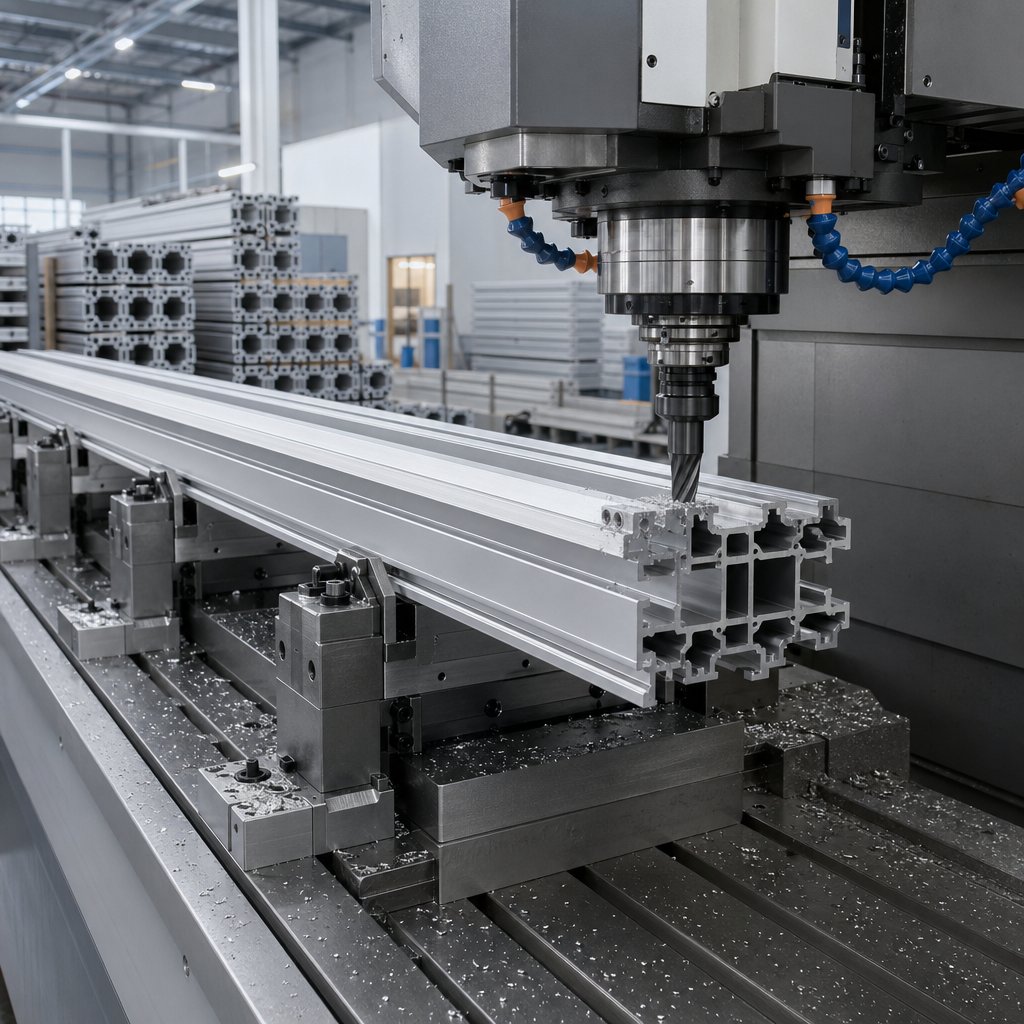
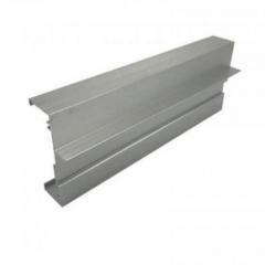
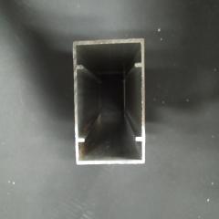
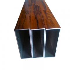
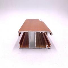
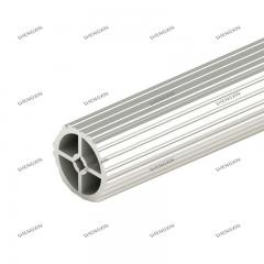
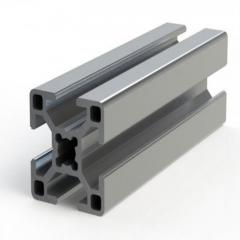
Some parts become expensive before machining even starts, simply because they begin from the wrong stock form. When a design keeps the same cross section over a long length, it is often smarter to extrude that shape first and machine only the holes, slots, end faces, and tight-tolerance features afterward. That approach suits rails, channels, enclosure frames, and similar profiles. Cerro Fabricated Products describes extrusion as the preferred route for high-volume parts with a constant cross section, while billet stays attractive for lower volumes, shorter lead times, and precision from solid stock. For lean aluminum parts manufacturing, that can mean less chip waste and fewer heavy roughing passes.
Billet and plate still have clear roles, especially when the geometry changes from one area to another. But if most of the profile is repetitive, carving the full shape from solid stock usually throws away time and material. Aluminum extrusion machining works best when the extrusion supplies the basic form and CNC adds only the critical details. That is also where an aluminum extrusion milling machine adds value: it is finishing the profile, not forcing the cutter to create the entire profile from scratch.
| Starting stock | Material utilization | Geometry fit | Machining effort | Finish implications |
|---|---|---|---|---|
| Billet | Lower when large volumes of material must be removed | Best for variable 3D shapes and lower-volume design changes | Highest if the final part needs extensive stock removal | Most visible surfaces are generated by machining, so texture is easier to standardize |
| Plate | Moderate for flat parts and broad profiles | Good for covers, brackets, and parts that start flat | Moderate, but rises with deep pockets or heavy contouring | Flat cosmetic faces and cut edges may need extra planning before finishing |
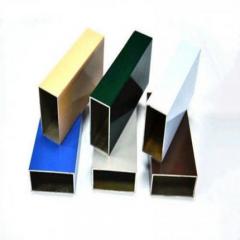
| Extrusion | Higher when the cross section stays constant along the length | Best for long profiles, channels, rails, and repeatable sections | Reduced to critical features, end work, and local precision cuts | Mill finish, anodizing, powder coating, and other profile finishes can be planned early, as shown by Shengxin Aluminum |
Extrusion is not automatically the cheaper answer. Cerro also notes higher initial setup cost and the limitation of one cross section at a time, so the die makes the most sense when repeat demand is real. That balance matters in higher-volume aluminum parts manufacturing, where scrap reduction helps, but tooling still has to earn its place.
The strongest extruded aluminum cnc programs usually come from suppliers that can manage die design, extrusion, CNC, and finishing as one plan. That reduces handoffs and helps preserve both dimensions and cosmetic intent. As a practical example, Shengxin Aluminum publishes combined CNC machining and custom aluminum extrusion capabilities, along with finishes such as anodizing, powder coating, polishing, and hard anodized processing. Its published profile range also supports custom aluminum products up to 6 meters in length, which is useful when an aluminum extrusion cnc workflow feeds directly into an aluminum extrusion milling machine for secondary features.
At that point, the RFQ stops being just a part drawing. It becomes a process brief, with the starting stock, machined zones, finish sequence, and critical dimensions all needing to be spelled out clearly.
Once a part moves from design review to sourcing, the drawing stops being just geometry. It becomes instructions for stock, machining, finish, inspection, packaging, and timing. That is where many delays begin. MakerStage's RFQ checklist notes that incomplete RFQs often trigger 3-5 business days of extra back-and-forth, while complete packages can often be quoted within 24 hours. That gap matters whether you are working with a local aluminum machine shop, comparing global aluminum machining services, or looking for a specialized aluminum cnc machining service.
Those gaps often cause the same two problems: the shop either prices extra risk into the quote or sends a long clarification list. The lowest price can also be misleading if scope, finish, or quality requirements are not actually matched.
Norck's supplier guidance points buyers toward five practical checks: material experience, machine capability, inspection discipline, communication, and DFM support. In plain terms, a strong aluminum cnc machining service or aluminium cnc service should do more than return a number. It should challenge unclear tolerances, flag risky geometry, and explain how finish choices affect lead time and inspection.
If a project combines extrusion, machining, and finishing, one useful example is Shengxin Aluminum, which supports both custom extrusion and CNC work for industrial applications. That kind of combined support can simplify handoffs when one supplier needs to manage the profile, secondary machining, and surface treatment together. In the end, the cleanest quotes usually come from the clearest brief and the most candid technical conversation.
For many parts, 6061-T6 is the best starting point because it offers a strong balance of machinability, corrosion resistance, weldability, availability, and finishing flexibility. It is not the only option, though. 7075 suits higher-load parts, 2024 fits fatigue-focused applications, 5052 works well in corrosion-heavy or formed designs, 6082 is useful for structural sections, and MIC-6 is often chosen for flat, stable tooling plates.
6061-T6 is usually better for general-purpose components because it is easier to source, easier to anodize consistently, and less risky when corrosion resistance and weldability matter. 7075 is the stronger choice when weight reduction and high load capacity drive the design, but it is less forgiving in welding and service environments. If the extra strength is not truly required, 6061 often gives a smoother manufacturing path.
Aluminum is soft and ductile, so it can smear, stretch, or stick to the cutting edge instead of separating cleanly. Burrs and built-up edge often point to dull tooling, weak chip evacuation, poor lubrication, excessive tool overhang, or recutting hot chips. The usual fix is to restore a sharp shearing cut, improve chip control, and keep thin or flexible features better supported during machining.
Yes. Some finishes add surface buildup, while others slightly change texture or edge condition, so a part that measures correctly after machining may fit differently after finishing. This matters most on bores, threads, press fits, sealing surfaces, and tight mating features. Buyers should always state whether critical dimensions apply before or after the finish so inspection and process planning match the real product requirement.
Extrusion plus CNC is often the smarter route when a part keeps the same cross section over a long length, such as rails, channels, frames, or enclosure members. The extrusion creates the base profile efficiently, and CNC machining adds the precision holes, slots, end work, and local features. For projects needing both operations, a supplier with combined extrusion, machining, and finishing capability, such as Shengxin Aluminum, can reduce handoffs and keep finish planning more coordinated.


 Интернет Сервис
 0086 136 3563 2360
 sales@sxalu.com
 +86 136 3563 2360
 русский
 English
 français
 Deutsch
 español
 português
 العربية
 ไทย
ไทย Việt
Việt Українська